Page 515
4A Preliminary (P3 and P15)
1. Disconnect the inlet and outlet-
piping before unbolting the
pump. If the pipes are corroded,
use penetrating oil on the
threads to aid in removal.
2. Unbolt the pump from the base
and remove. Disassembly
instructions for the pump are
found in section 4, T51 PUMP
ENDS. All work on the unit
should be performed on an
elevated workbench whenever
possible.
The disassembly and reassembly
procedures are broken into two
sections covering the following
units:
4B — Disassembly of the P3 and
P15 Bearing Pedestals
4D — Reassembly of the P3 and
P15 Bearing Pedestals
Exploded views of each unit,
Figures 4-19 and 4-20 are provided
for referencing the numbers in the
following procedures, i.e. flinger
(#21).
4B Disassembly (P3 and P15)
The following tools and equipment
are needed for disassembly of the
P3 and P15 units:
4.
1. Soft plastic or wooden mallet.
2. Arbor press or vise.
3. 3/4" X 6" piece of water pipe for
P3, 1-1/4" X 6" for P15.
4. Internal snap ring plier.
5. Penetrating oil.
When installing or removing
bearings from the shaft, the use of
an arbor press is strongly recom-
mended.
To disassemble the pedestal:
Refer to Figures 4-19 and 4-20 for
reference to the numbered parts in
the procedures below.
1. Remove the flinger (#21) located
in the pump end of the bearing
pedestal (#3).
2. Using a snap ring plier, remove
snap ring (#4).
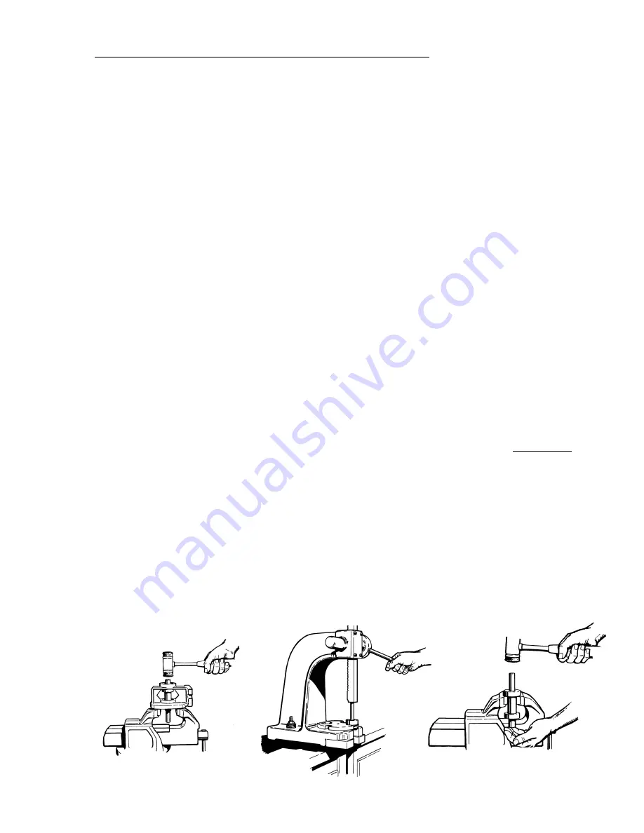
3. Open the jaws of the vice
approximately 2-1/4" for model
P3 and 3" for model P15.
4. Place the pedestal, pump side
down, on the jaws. Refer to
Figure 4-18.
5. Using a plastic or wooden mallet,
gently tap on the end of the shaft
until it slides out of the frame.
Both bearings should come out
with the shaft. Do not use a
metal hammer; severe damage
to the shaft will occur.
6. Using the arbor press remove
the two (2) bearings from the
shaft. Refer to Figure 4-21. If the
inner race is well supported
during this operation, no damage
will be done to the bearings.
If an arbor press is not available, a
bench vise may be substituted
using the following instructions.
1. Remove the pedestal and close
the jaws to approximately 1-1/8"
for model P3 and 1-3/8" for
model P15.
2. Place the shaft with either
bearing resting on top of the jaws
and gently tap on the end of the
shaft until the bearing is re-
moved. Refer to Figure 4-22.
3. Repeat step 2 to remove the
other bearing. Good support
used on the inner races will
prevent bearing damage.
4C Inspection of Components
Thoroughly clean all parts. All
components should be examined
for wear and corrosion. Replace
any parts showing visible wear.
Check to be certain that a press fit
still exists between the shaft and
the bearings. New bearings, or at
least cleaned and regreased
bearings, are recommended.
Check the shaft for galling, pitting,
and corrosion. Surface corrosion
on the pump portion of the shaft
must be removed so the seals will
slide freely during assembly. The
shaft diameter should be no smaller
than .002" below the nominal
fractional seal sizes. Remove any
nicks or burrs which may have
occurred during disassembly.
Reclean parts as necessary.
Figure 4-22
Figure 4-18
Figure 4-21
A. Preliminary
B. Disassembly
C. Inspection of Components
D. Reassembly
E. Testing and Final Adjustments
BEARING PEDESTALS
Service
T51 SERIES


