Hardware Installation
4-4
4
2.
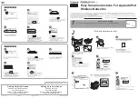
Position the bracket in the intended location and mark the position of the three
mounting screw holes.
3.
Drill three holes in the wall that match the screws and wall plugs included in the
bracket kit, then secure the bracket to the wall.
4.
Use the included nuts to tightly secure the wireless bridge to the bracket.
Connect External Antennas
When deploying a MRW55M Master bridge unit for a bridge link or access point
operation, you need to mount external antennas and connect them to the bridge.
Typically, a bridge link requires a 5 GHz antenna, and access point operation a
2.4 GHz antenna. MRW55 Slave units also require an external antenna for 2.4 GHz
operation.
Perform these steps:
1.
Mount the external antenna to the same supporting structure as the bridge,
within 3 m (10 ft) distance, using the bracket supplied in the antenna package.
2.
Connect the antenna to the bridge’s N-type connector using the RF coaxial
cable provided in the antenna package.
3.
Apply weatherproofing tape to the antenna connectors to help prevent water
entering the connectors.
RF Coaxial Cable
2.4 GHz External
Omnidirectional
Antenna
2.4 GHz
N-type Connector
5 GHz
N-type Connector
5 GHz External
High-gain Panel
Antenna
MRW55M
Summary of Contents for MRW55
Page 1: ...MRW55 MRW55M Dual Band Outdoor Access Point Bridge User Guide...
Page 2: ......
Page 4: ...MRW55 MRW55M E022005 R01...
Page 12: ...viii...
Page 32: ...Network Configuration 2 6 2...
Page 40: ...Bridge Link Planning 3 8 3...
Page 58: ...Initial Configuration 5 10 5...
Page 216: ...Troubleshooting A 2 A 5 If you forgot or lost the password Contact Technical Support...
Page 234: ...D 2 Customer Support D...
Page 238: ...Glossary Glossary 4...
Page 242: ...Index 4 Index...
Page 243: ......
Page 244: ...MRW55 MRW55M E022005 R01...


