Restarting the System
MVME166IG/D2
3-11
3
controller scanning sequence goes from the lowest controller Logical Unit
Number (LUN) detected to the highest LUN detected. (Refer to Appendix C
for default LUNs.)
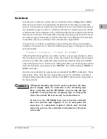
At power-up, Network Boot is enabled, and providing the drive and controller
numbers encountered are valid, the following message is displayed upon the
system console:
"Network Boot in progress... To abort hit <BREAK>"
Following this message there is a delay to allow you to abort the Auto Boot
process if you wish. Then the actual I/O is begun: the program pointed to
within the volume ID of the media specified is loaded into RAM and control
passed to it. If, however, during this time you want to gain control without
Network Boot, you can press the <BREAK> key or the software ABORT or
RESET switches.
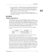
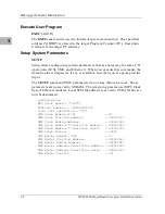
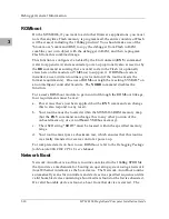
Network Auto Boot is controlled by parameters contained in the NIOT and
ENV
commands. These parameters allow the selection of specific boot
devices, systems, and files, and allow programming of the Boot delay. Refer
to the ENV command in Appendix A for more details.
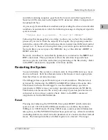
Restarting the System
You can initialize the system to a known state in three different ways: reset,
abort, and break. Each has characteristics which make it more appropriate
than the others in certain situations.
The debugger has a special feature upon a reset condition. This feature is
activated by depressing the RESET and ABORT switches at the same time.
This feature instructs the debugger to use the default setup/operation
parameters in ROM versus your setup/operation parameters in NVRAM.
This feature can be used in the event your setup/operation parameters are
corrupted or do not meet a sanity check. Refer to the ENV command
(Appendix A) for the ROM defaults.
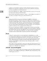
Reset
Pressing and releasing the MVME166 front panel RESET switch initiates a
system reset. COLD and WARM reset modes are available. By default,
166Bug is in COLD mode. During COLD reset, a total system initialization
takes place, as if the MVME166 had just been powered up. All static variables
(including disk device and controller parameters) are restored to their default
states. The breakpoint table and offset registers are cleared. The target
Summary of Contents for MVME166
Page 1: ...MVME166 Single Board Computer Installation Guide MVME166IG D2 ...
Page 12: ...xii ...
Page 14: ...xiv ...
Page 46: ...Hardware Preparation and Installation 2 10 MVME166 Single Board Computer Installation Guide 2 ...
Page 70: ...Debugger General Information 3 24 MVME166 Single Board Computer Installation Guide 3 ...
Page 114: ...Disk Tape Controller Data B 6 MVME166 Single Board Computer Installation Guide B ...
Page 116: ...Network Controller Data C 2 MVME166 Single Board Computer Installation Guide C ...

