MVME166IG/D21-1
1
BOARD LEVEL
HARDWARE DESCRIPTION
Introduction
This chapter describes the board level hardware features of the MVME166
Single Board Computers. The chapter is organized with a board level
overview and features list in this introduction, followed by a more detailed
hardware functional description. Front panel switches and indicators are
included in the detailed hardware functional description. The chapter closes
with some general memory maps.
All programmable registers in the MVME166 that reside in ASICs are covered
in the MVME166/MVME167/MVME187 Single Board Computers Programmer’s
Reference Guide.
Overview
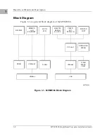
The MVME166 is based on the MC68040 microprocessor. The MVME166 has
4/8/16/32/64/128/256 MB of ECC-protected DRAM, 1 MB of Flash memory
with download EPROM, 128KB of static RAM (with battery backup), 8KB of
static RAM and time of day clock (with battery backup), Ethernet transceiver
interface, four serial ports with TTL interface, four tick timers, watchdog timer,
SCSI bus interface with DMA, Centronics printer port,
A16/A24/A32/D8/D16/D32/D64 VMEbus master/slave interface, VMEbus
system controller, and a VSB interface.
The I/O connection for the MVME166 is provided by two high density
shielded front panel I/O connectors. The SCSI bus is connected through a 68
pin connector. The printer, four serial ports and Ethernet interface are
connected through a 100 pin connector. The MVME712-10 transition module
and the MVME712-06/07/09 I/O distribution board set were designed to
support the MVME166 boards. These transition boards provide configuration
headers, serial port drivers and industry standard connectors for the I/O
devices.
The VMEbus interface is provided by an ASIC called the VMEchip2. The
VMEchip2 includes two tick timers, a watchdog timer, programmable map
decoders for the master and slave interfaces, and a VMEbus to/from local bus
DMA controller, a VMEbus to/from local bus non-DMA programmed access
interface, a VMEbus interrupter, a VMEbus system controller, a VMEbus
interrupt handler, and a VMEbus requester.
Summary of Contents for MVME166
Page 1: ...MVME166 Single Board Computer Installation Guide MVME166IG D2 ...
Page 12: ...xii ...
Page 14: ...xiv ...
Page 46: ...Hardware Preparation and Installation 2 10 MVME166 Single Board Computer Installation Guide 2 ...
Page 70: ...Debugger General Information 3 24 MVME166 Single Board Computer Installation Guide 3 ...
Page 114: ...Disk Tape Controller Data B 6 MVME166 Single Board Computer Installation Guide B ...
Page 116: ...Network Controller Data C 2 MVME166 Single Board Computer Installation Guide C ...


