


40
MOTOROLA
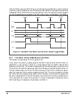
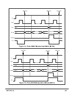
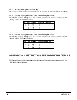
6.4.5
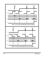
Timer Mode 5 (Period Measurement Mode)
Timer Mode 5 is defined by TC2-TC0 equal to 101.
In Timer Mode 5, the counter is driven by a clock derived from the DSP’s internal clock
divided by 2 (CLK/2). With the timer enabled (TE=1), the counter is loaded with the value
contained by the TCR and starts incrementing. On each transition of the same polarity that
occurs on TIO, the TS bit in TCSR is set and, if TIE is set, an interrupt is generated. The
contents of the counter is loaded in the TCR. The user’s program can read the TCR and
subtract consecutive values of the counter to determine the distance between TIO edges.
The counter is not stopped and it continues to increment. The INV bit determines whether
the period is measured between 0-to-1 transitions of TIO (INV=0), or between 1-to-0 tran-
sitions of TIO (INV=1). Figure 16 illustrates Timer Mode 5 when INV=0, and Figure 17
illustrates Mode 5 with INV=1.
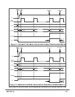
6.4.6
Timer Mode 7 (Event Counter Mode, External Clock)
Timer Mode 7 is defined by TC2-TC0 equal to 111.
With the timer enabled (TE=1), the counter is loaded with the value contained by the TCR.
The counter is decremented by the transitions of the signal coming in on the TIO input pin.
At the transition that occurs after the counter has reached 0, the TS bit in TCSR is set and,
if the TIE is set, the timer generates an interrupt. The counter is reloaded with the value
contained by the TCR, and the entire process is repeated until the timer is disabled
(TE=0). The INV bit determines whether 0-to-1 transitions (INV=0) or 1-to-0 transitions
(INV=1) will decrement the counter. Figure 18 illustrates Timer Mode 7 when INV=0, and
Figure 19 illustrates Timer Mode 7 when INV=1.
Summary of Contents for DSP96002
Page 3: ...1 2 DSP96002 USER S MANUAL MOTOROLA ...
Page 38: ...MOTOROLA DSP96002 USER S MANUAL 3 15 Figure 3 4 Modulo Arithmetic Unit Block Diagram ...
Page 39: ...3 16 DSP96002 USER S MANUAL MOTOROLA ...
Page 53: ...4 14 DSP96002 USER S MANUAL MOTOROLA ...
Page 76: ...MOTOROLA DSP96002 USER S MANUAL 5 23 Figure 5 8 Address Modifier Summary ...
Page 86: ...6 10 DSP96002 USER S MANUAL MOTOROLA ...
Page 101: ...MOTOROLA DSP96002 USER S MANUAL 7 15 Figure 7 9 HI Block Diagram One Port ...
Page 140: ...7 54 DSP96002 USER S MANUAL MOTOROLA ...
Page 166: ...9 10 DSP96002 USER S MANUAL MOTOROLA ...
Page 181: ...MOTOROLA DSP96002 USER S MANUAL 10 15 Figure 10 8 Program Address Bus FIFO ...
Page 337: ...MOTOROLA DSP96002 USER S MANUAL A 149 ...
Page 404: ...A 216 DSP96002 USER S MANUAL MOTOROLA PC xxxx D ...
Page 460: ...A 272 DSP96002 USER S MANUAL MOTOROLA SIOP Not affected ...
Page 484: ...A 296 DSP96002 USER S MANUAL MOTOROLA SSH PC SSL SR SP 1 SP ...
Page 519: ...MOTOROLA DSP96002 USER S MANUAL A 331 ...
Page 718: ...MOTOROLA DSP96002 USER S MANUAL B 199 ...
Page 871: ... MOTOROLA INC 1994 MOTOROLA TECHNICAL DATA SEMICONDUCTOR M Addendum ...
Page 888: ...MOTOROLA INDEX 1 INDEX ...
Page 889: ......


