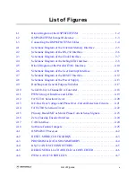
List of Figures
v
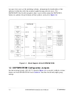
Block Diagram of the DSP56F807EVM . . . . . . . . . . . . . . . . . . . . . . . . . 1-2
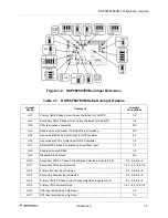
DSP56F807EVM Jumper Reference . . . . . . . . . . . . . . . . . . . . . . . . . . . . 1-3
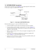
Connecting the DSP56F807EVM Cables . . . . . . . . . . . . . . . . . . . . . . . . . 1-4
Schematic Diagram of the External Memory Interface . . . . . . . . . . . . . . 2-5
Schematic Diagram of the RS-232 Interface . . . . . . . . . . . . . . . . . . . . . . 2-6
Schematic Diagram of the Clock Interface . . . . . . . . . . . . . . . . . . . . . . . . 2-7
Schematic Diagram of the Debug LED Interface . . . . . . . . . . . . . . . . . . . 2-8
Block Diagram of the Parallel JTAG Interface. . . . . . . . . . . . . . . . . . . . 2-10
Schematic Diagram of the User Interrupt Interface . . . . . . . . . . . . . . . . 2-11
Schematic Diagram of the RESET Interface . . . . . . . . . . . . . . . . . . . . . 2-12
Schematic Diagram of the Power Supply . . . . . . . . . . . . . . . . . . . . . . . . 2-13
Run/Stop and General Purpose Switches . . . . . . . . . . . . . . . . . . . . . . . . 2-17
Serial 10-bit, 4-Channel D/A Converter . . . . . . . . . . . . . . . . . . . . . . . . . 2-18
PWM Group A Interface and LEDs . . . . . . . . . . . . . . . . . . . . . . . . . . . . 2-19
FAULTA1 Selection Circuit. . . . . . . . . . . . . . . . . . . . . . . . . . . . . . . . . . 2-20
DC-Bus Over-Voltage and Phase Over-Current Detection Circuits. . . . 2-21
FAULTB1 Selection Circuit . . . . . . . . . . . . . . . . . . . . . . . . . . . . . . . . . . 2-22
Primary Back-EMF or Motor Phase Current Sense Signals . . . . . . . . . . 2-23
Zero-Crossing Encoder Interface . . . . . . . . . . . . . . . . . . . . . . . . . . . . . . 2-24
RESET, MODE,CLOCK &IRQS. . . . . . . . . . . . . . . . . . . . . . . . . . . . . . . A-3
PROGRAM & DATA SRAM MEMORY . . . . . . . . . . . . . . . . . . . . . . . . A-4
RS-232 AND SCI CONNECTORS . . . . . . . . . . . . . . . . . . . . . . . . . . . . . A-5
DEBUG SERIAL 4-CHANNEL D/A CONVERTER . . . . . . . . . . . . . . . A-6
PWM A AND 3 USER LEDS . . . . . . . . . . . . . . . . . . . . . . . . . . . . . . . . . A-7
List of Figures
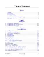
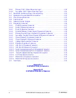
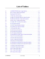
Summary of Contents for Digital DNA DSP56F807
Page 2: ......
Page 12: ...xii DSP56F807EVM Hardware User s Manual ...
Page 53: ... DSP56F807EVM Schematics A 1 Appendix A DSP56F807EVM Schematics ...
Page 72: ...A 20 DSP56F807EVM Hardware User s Manual ...
Page 79: ......


