2-18
DSP56F807EVM Hardware User’s Manual
2.14 Serial 10-bit 4-channel D/A Converter
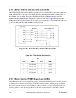
The DSP56F807EVM board contains a serial 10-bit, 4-channel D/A converter connected
to the DSP56F807’s SPI port. The output pins are uncommitted and are connected to a
4X2 header, J26, to allow easy user connections. Refer to
for the D/A
connections and
for the header’s pin out. The D/A’s output full-scale range
value can be set to a value from 0.0V to 2.4V by a trimpot, R97. This trimpot is preset to
+2.05V which provides approximately 2mV per step.
Figure 2-10. Serial 10-bit, 4-Channel D/A Converter
2.15 Motor Control PWM Signals and LEDs
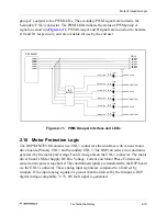
The DSP56F807 has two independent groups of dedicated PWM units. Each unit contains
six PWM, three Phase Current sense and four Fault input lines. PWM group A’s PWM
lines are connected to the UNI-3 interface connector and to a set of six PWM LEDs via
inverting buffers. The inverting buffers are used to isolate and drive the DSP’s PWM
Table 2-8. D/A Header Description
J20
Pin #
Signal
Pin #
Signal
1
D/A Channel 0
2
AGND
3
D/A Channel 1
4
AGND
5
D/A Channel 2
6
AGND
7
D/A Channel 3
8
AGND
DSP56F807
MAX5251
D/A CONNECTOR
MOSI
MISO
SCLK
PB4
RSTO
DIN
DOUT
SCLK
CS
CL
OUT A
OUT B
OUT C
OUT D
Vref
1
3
5
7
2
4
6
8
D/A 0
D/A 1
D/A 2
D/A 3
J26
+3.3VA
10K
R97
Summary of Contents for Digital DNA DSP56F807
Page 2: ......
Page 12: ...xii DSP56F807EVM Hardware User s Manual ...
Page 53: ... DSP56F807EVM Schematics A 1 Appendix A DSP56F807EVM Schematics ...
Page 72: ...A 20 DSP56F807EVM Hardware User s Manual ...
Page 79: ......

