2-24
DSP56F807EVM Hardware User’s Manual
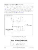
Figure 2-16. Zero-Crossing Encoder Interface
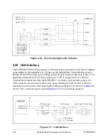
2.20 CAN Interface
The DSP56F807EVM board contains a CAN physical-layer interface chip that is attached
to the MSCAN_RX and MSCAN_TX pins on the DSP56F807. The EVM board uses a
Philips, PCA82C250, high speed, 1Mbps, physical layer interface chip. Due to the +5.0V
operating voltage of the CAN chip, a pull-up to +5.0V is required to level shift the
Transmit Data output line from the DSP56F807. A primary, J24, and daisy-chain, J25,
CAN connector are provided to allow easy daisy-chaining of CAN devices. CAN bus
termination of 120 ohms can be provided by adding a jumper to JG3. Refer to
for the CAN connector signals, and to
for a connection diagram
Figure 2-17. CAN Interface
ZERO_X_A
ZERO_X_B
ZERO_X_C
1
2
3
4
5
6
+5.0V
FILTER
FILTER
FILTER
FILTER
PIN 1: +5.0V
PIN 2: GROUND
PIN 3: PHASE A
PIN 4: PHASE B
PIN 5: INDEX
PIN 6: HOME
1
2
3
4
5
6
7
8
9
JG12
DSP56F807
PHASEA1
PHASEB1
INDEX1
HOME 1
DSP56F807
MSCAN_TX
MSCAN_RX
CAN Transceiver
CAN Connector
Daisy-Chain CAN Connector
TXD
RXD
SLOPE
VREF
VCC
GND
CANL
+5.0V
+5.0V
PCA82C250T
1
3
5
7
9
2
4
6
8
10
1
3
5
7
9
2
4
6
8
10
x
x
x
x
x
x
x
x
x
x
x
x
x
x
JG3
J24
1
2
120
CAN Bus
Terminator
1K
CANH
J25
Summary of Contents for Digital DNA DSP56F807
Page 2: ......
Page 12: ...xii DSP56F807EVM Hardware User s Manual ...
Page 53: ... DSP56F807EVM Schematics A 1 Appendix A DSP56F807EVM Schematics ...
Page 72: ...A 20 DSP56F807EVM Hardware User s Manual ...
Page 79: ......

