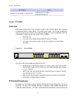
Chapter 2: Network Setup
in order to prevent the switch from dropping these discovery packets. See Appendix A for
detailed steps on how to configure the IP directed broadcast feature on the 3750 L3 switch.
VLAN Setup
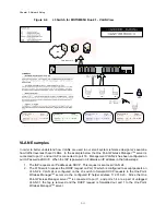
The L3 network switch provides the ability to segment management and user traffic using a
combination of VLAN tagging and firewall access control rules, see Figure 2-4. In the small
system reference design the L3 switch has been configured with the following 4 VLANs each
representing a different IP subnet per our IP plan:
•
VLAN 31 is configured on Ports 1-4. Ports 1-4 are access ports only (non-tagged)
and are used by network servers such as the One Point Wireless Manager™ server
(172.31.0.20/16) and RADIUS. VLAN 31 has the address of 172.31.0.2/16. Note
how the second octet of the IP address (31) is aligned with the VLAN number. This
has been done to simplify the IP design.
•
VLAN 1 is the native VLAN of the L3 switch by default. Ports 5-24 have been
configured as trunked ports and have VLAN 1 in their allowed VLAN list. VLAN 1 has
the IP address of 10.1.0.1/24. It has been configured to support non VLAN capable
devices such as cameras and other IP devices. This VLAN is also configured with an
IP helper address of 172.31.0.20 (The address of the Wireless One Point Manager™
server) to service any DHCP requests received on this VLAN.
•
VLAN 24 is also included in the allowed VLAN list on ports 5-24. VLAN 24 has the
address of 10.24.0.1/16. VLAN 24 has been configured to be used as a
management VLAN. The management VLAN is used to communicate management
data from the One Point Wireless Manager™ application to IAPs and MWRs. This
VLAN is also configured with an IP helper address of 172.31.0.20 (The address of
the Wireless One Point Manager™ server) to service any DHCP requests received
on this VLAN.
•
VLAN 49 is also included in the allowed VLAN list on ports 5-24. VLAN 49 has the
address of 10.49.0.1/16. VLAN 49 has been configured to be used by wireless
clients. As mentioned previously a MOTOMESH Duo device supports up to 15
Virtual Access Points (VAPs) per radio. Each VAP can be configured to have a
unique VLAN. Thus, in this example, VLAN 49 has been created to support a client
VAP. Note that this VLAN tag will be stripped off prior to data being sent to client
devices (VLAN tag stripping is on by default on client VAPs). Traffic that originates
from a client would be tagged with VLAN 49. This VLAN is also configured with an IP
helper address of 172.31.0.20 (The address of the Wireless One Point Manager™
server) to service any DHCP requests received on this VLAN.
2-10
Summary of Contents for 2.1
Page 2: ...This page intentionally left blank ii ...
Page 4: ...This page intentionally left blank iv ...
Page 10: ...This page intentionally left blank x ...
Page 12: ...This page intentionally left blank xii ...
Page 14: ...This page intentionally left blank xiv ...
Page 59: ...Chapter 3 MOTOMESH Duo Hardware This page intentionally left blank 3 12 ...
Page 86: ...Chapter 5 Customer Information This page intentionally left blank 5 7 ...
Page 123: ......
Page 131: ...Appendix A Figure 9 39 General Settings Tab in the Web User Interface 9 30 ...


