


60
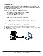
Networking and Communication
5.5 Ethernet
!
CAUTION: Risk of Tampering
The TS-MPPT-600V does not feature built-in network security. It is the responsibility of the user or
network administrator to place the TS-MPPT-600V-TR behind a network firewall to prevent unauthorized
access.
!
PRUDENCE : Risque de tentative d’altération
Le TS-MPPT-600V ne comporte pas de sécurité réseau intégrée. Il incombe à l’utilisateur ou à
l’administrateur du réseau de placer le TS-MPPT-600V-TR derrière un pare-feu réseau afin d’empêcher
l’accès non autorisé.
The Ethernet port supports HTTP, MODBUS TCP/IP
TM
, SMTP, and SNMP protocols to provide
a fully web-enabled interface between the TS-MPPT-600V-TR and a LAN/WAN network or the
internet.
Ethernet connections also provide the communication link between multiple TS-MPPT-600V-TR
controllers for synchronous operation. Some of the many features the Ethernet connection pro-
vides include:
•
program custom settings with MSView
TM
PC software
•
monitor the controller from a web browser
•
link up to four controllers for synchronous operation
•
modify controller settings from a web browser
•
log and monitor the system with MSView
TM
PC software anywhere on the internet
•
create custom web pages to show system data
• send an email or text message if a fault, alarm, or user-defined event occurs
•
monitor and receive messages on an SNMP network
This section provides a summary of each of the features. For detailed information about Ethernet
connectivity and networking, refer to the “Morningstar Communications Document” on our
website at: http://www.morningstarcorp.com
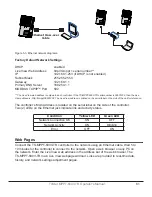
Network Information
Connect to the TS-MPPT-600V-TR via an Ethernet network (LAN/WAN) or connect the controller
directly to a PC using an ethernet cross-over cable. Use CAT-5 or CAT-5e twisted pair Ethernet
cables with RJ-45 connectors. A network diagram for both scenarios is shown in figure 5-3 below.


