


22
Installation
1
2
3
4
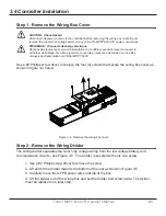
Figure 3-5. Remove the Wiring Divider.
Step 3 - Remove the Knock-Outs
Plan the routing of each conductor that will connect to the TS-MPPT-600V-TR before removing
any knock-outs. The 1/2” (M20) knock-outs are ideal for routing network cables, which must be
placed in separate conduit.
Use a flat head screwdriver to remove the necessary knock-outs. A hammer may also be
required to apply extra force. Refer to Section 3.2 for detailed knockout information.
WARNING: Shock Hazard
Always use bushings, connectors, clamp connectors, or wire glands in the knock-out openings to
protect wiring from sharp edges.
PRUDENCE : Risque de décharge électrique
Utilisez toujours des bagues, des connecteurs, des raccordements à collets ou des fouloirs dans
les ouvertures afin de protéger le câblage des bords coupants.
WARNING: Shock Hazard
Never route network cables in the same conduit as the power conductors.
AVERTISSEMENT: Risque de décharge électrique
N’acheminez jamais les câbles réseau dans le même conduit que les conducteurs
d’alimentation.


