background image

Morehouse Instrument Company, Inc.

1742 Sixth Ave., York, PA 17403-2675 USA

Phone: (717) 843-0081

www.mhforce.com

Page 36

Rev. 3/2022

4215-HS Indicator

Manual

(PM-4101)

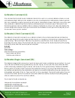
Limit Set Command (LiS)

The Limit Set (LiS) command is broken up into 4 separate commands. They have the following format:  

L(limit number)SA(space) (normal position)(enable)(item number)(unit number) 

L(limit number)SB(space) (setpoint number)# 

L(limit number)SC(space) (< or >)(latching) 

L(limit number)SD(space) (reset point number)# 

The limit number chooses which limit (1-4) you want to setup. The normal position should be set to 0 for 

normally open or 1 for normally closed. The enable should be set to 0 for disabled or 1 for enabled. If the limit 

is disabled the rest of this command may be omitted (see example 3). The item and unit numbers indicate 

which signal is to drive this limit. The set point number indicates the signal level at which the limit is to be 

activated. The < or > sign indicates whether you want the limit to be activated when the signal is greater than 

the set point (>) or less than the set point (<). The latching should be set to 0 for latching off or 1 for latching 

on. If latching on is selected the rest of the command may be omitted (see example 2). Latching on will require 

a manual reset once the limit has been activated. The reset point indicates the signal level at which the limit 

should be de-activated. 

If you want to enable a limit without otherwise changing its settings you can enter L(limit number)SA(space)

(normal position)1#  instead of entering the full setup string (see example 4). 

Example 1: 

@123L1SA 010000 

Acknowledge 1: 

@123  Limit Setup Command A – Ready for Command B 

Example 2: 

@123L1SB 50.0# 

Acknowledge 1: 

@123  Limit Setup Command B – Ready for Command C 

Example 3: 

@123L1SC >0 

Acknowledge 3: 

@123  Limit Setup Command C – Ready for Command D 

Example 4: 

@123L1SD 10.0# 

Acknowledge 4: 

@123  Lim 1 NO  Enabled Load A Lb Set  50.00 Trip>Set Latch Off Reset  10.00 

Summary of Contents for 4215

Page 1: ...LI Z540 3 Accredited Morehouse Instrument Company Inc 1742 Sixth Ave York PA 17403 2675 USA P 717 843 0081 F 717 846 4193 info mhforce com www mhforce com PM 4101 Rev 3 2022 Operation and Instruction Manual 4215 HS Indicator ...

Page 2: ...15 HS Indicator Manual PM 4101 Table of Contents Introduction 3 Quick Start 4 Run Mode 6 Setup Mode Summary 9 Remote Operation 19 RS232 Run Mode Command Summary 20 Rs232 Setup Mode Command Summary 25 System Calibration Mode 43 Force Averaging Optional 43 Appendix A 4215 HS Specifications 45 Appendix B Cables and Connectors 47 ...

Page 3: ...ser friendly front panel menus Keylock option to prevent accidental or unauthorized changes to the unit s setup Measure load in pounds kilograms Newtons PSI MegaPascals kilo pounds kiloNewtons metric tons mV V or grams User defined base area for PSI and MPa Tare at any time Capture the load peak and valley display in pounds kilograms Newtons PSI MegaPascals kilo pounds kilo Newtons metric tons or ...

Page 4: ...efined scale factor and offset Large buffered 10 00 volt output Remote operation using standard RS232 ASCII command set Back panel digital inputs for tare peak and valley reset position reset and print Other functions available as custom programmed options Optionally measure the average force using a contact closure to begin and end the averaging period This section will help you get your Model 42...

Page 5: ...is button will cycle through the list of units available for the currently displayed item For example with Load A showing you would see Lb kg N PSI MPa Klb kN t mV V g and then back to Lb Message Meaning 1 ESL X Y Z This is the version number 2 Serial 12345 Option 114236 This is the serial number This is the option number 3 Last ID A 90437 Last ID B 12030 The serial number of the load cell on Ch A...

Page 6: ...15 HS at all times The display just selects which par ticular item you wish to see and what units are used to display or print this data The row of buttons have the functions indicated by the upper set of labels Item Tare Reset View Print Unit Each of these is described below Message Meaning Load A Pounds Kilograms Newtons PSI MegaPascals Kilo Pounds Kilo Newtons Metric Tons mV V grams Peak A Poun...

Page 7: ...llowing menu will appear Reset Ch A Ch B will reset the peak valley max min for channels A and B Reset Ch A Only will reset the peak and valley for channel A Reset Ch B Only will reset the max and min for channel B Reset Position will reset the position to zero Reset Limits will reset any limits that require manual resetting For a single channel unit the following menu will appear Reset Peak Vall ...

Page 8: ...itch back and forth between Load in Lb and Peak in PSI with a single button push If you choose to have the second line show a display then the View button toggles between the display currently being activated The activated display will have a symbol to the left of it Print Button T The Print button will send a set of data to the printer This will contain the current readings of load peak val ley p...

Page 9: ...A 17403 2675 USA Phone 717 843 0081 www mhforce com Page 9 Rev 3 2022 4215 HS Indicator Manual PM 4101 The table below summarizes the setup mode menus Detailed information about each individual item is presented in the following sections Setup Mode Summary ...

Page 10: ... is used to select the analog channel source and scaling for the analog output channels Sensor Select lets you manually set which load cell calibration data is used If you use auto id load cells you will never need this menu Calibration provides access to calibration for load cells extension sensor or optical encoders Limits allows you to set the source and options for the 4 contact closure switch...

Page 11: ... to the hundredths place Plus increments the digit above the cursor Thus 12 34 becomes 13 34 Note that 9 will wrap around to 0 Minus decrements the digit above the cursor Thus 12 34 becomes 11 34 Note that 0 will wrap around to 9 Plus and Minus both and at the same time This will change the sign of the number Thus 12 34 be comes 12 34 Note that cursor position does not matter when you change the s...

Page 12: ...f source data in the selected units that will cause the Model 4215 HS to output positive full scale analog voltage 10 0 volts 5 Zero This entry specifies the value of source data in the selected units that will cause the Model 4215 HS to output zero analog voltage 0 0 volts Once you have entered these 4 selections the analog output is setup Sensor Select This menu is used to manually select load c...

Page 13: ...e re calibrating a load cell the Model 4215 HS will recognize it using either the autoid or a manually entered serial number Any time you overwrite existing load cell calibration data you will first be warned with the Overwrite Data message Pressing enter will overwrite pressing escape will cancel the calibration An other method of overwriting existing data is to delete the sensor first and then c...

Page 14: ...k if you want to calibrate by 2 Point 5 Point or 10 Point Non standard optional configuration You will then be asked for the channel the load cell serial number the date the cali bration unit the cell s maximum rated load and the desired excitation voltage 5 0 or 10 0 volts You are then prompted to enter the value of the first mass The Mass 1 Ready message will wait while you actually hang the mas...

Page 15: ...uttons to select the source of the data that will drive the limit The standard list will include load peak valley position velocity and optionally average force Press enter to select the displayed item 5 Units This entry allows you to scroll through the list of available units for the data source you have chosen in the previous step 6 Set This is the numerical value of the source at which the limi...

Page 16: ...e this baud rate for communication with your printer This setting has no effect on units that are not equipped with the printing option 57 6 K baud is commonly used on older serial printers 230 4 K baud is used on more recent serial printers Auto Identify TEDS Capability This allows you to turn automatic load cell identification on or off Usually you can leave auto id on even if you never use auto...

Page 17: ...ll retain tare on channel A in a single channel unit and both channels A and B in a twochannel unit Display Options This menu contains options that effect how load peak and valley are displayed and printed These are listed in a submenu that works exactly like the setup mode main menu Filter Select There are two types of filters available on the Model 4215 HS Type I and Type II Type I filters are g...

Page 18: ...ecimal digits shown may be limited for example a 100 Lb cell will allow 3 digits while a 1000 Lb cell will only allow 2 digits Also if a number is too large to fit on the display some decimal digits may be dropped the display will auto range The number of digits shown for position data depends only on the number of counts per inch of the encoder and is not effect ed by this setting Second Line Thi...

Page 19: ...mmands fall into two groups commands that are like Run Mode and commands are like Setup Mode The Model 4215 HS supports remote operation using a standard RS232 Interface consisting of ASCII characters The baud rate is set using the Com Baudrate item on the System Options menu Supported rates are 300 600 1200 2400 4800 9600 and 19 2k baud There must be 8 data bits no parity and 1 stop bit To suppor...

Page 20: ...ort description that includes the command format an example that shows what you would type shown in plain font and what the Model 4215 HS would return shown in italics Hello Command H This command fetches the model version and serial number of any unit at the specified address Example 123H Acknowledge 123 ESL Model 4215 HS Version 4 4 0 Serial 980500 Question Mark Command This command returns a li...

Page 21: ...d combination of item and unit There are three subcommands Front panel View FV Front panel Set FS and Front panel Alter nate FA Front Panel View Command FV The Front panel View FV command just tells you what is currently on the display and what will be displayed when the View button on the front panel is pressed Example 123FV Acknowledge 123 Active Display shows Load A in Lb Other Display shows Pe...

Page 22: ... number unit number channel A unit number channel B repeat where the item and unit numbers can be found using the question mark command see above and the repeat number must be 0 1 or 2 Choosing repeat 1 will make the tester send you the desired value once Choosing repeat 2 will make the tester send the value at approximately 3 second intervals Choosing repeat 0 will turn off any values that are be...

Page 23: ...proximately every three seconds like the value command Repeat 0 will turn off printing that was started with repeat 2 Repeat 3 will send one set of readings to the serial printer attached to the Model 4215 HS instead of to the RS232 terminal Example 123P1 Acknowledge 123 Load A 45 625 Lb Peak A 82 396 Lb Vall A 0 005 Lb Load B 22 560 Lb Peak B 23 000 Lb Vall B 0 0001 Lb Pos 3 500 In Vel 0 0 I M Av...

Page 24: ...Text Display Command T This command allows you to put a line of text on the front panel display of the Model 4215 HS The format is T text where text is the message that you want to display The text is limited to the number of characters that can be shown on the front panel display Example 123TStress Test Ready Acknowledge 123 Text Displayed Stress Test Ready ...

Page 25: ...Morehouse Instrument Company Inc 1742 Sixth Ave York PA 17403 2675 USA Phone 717 843 0081 www mhforce com Page 25 Rev 3 2022 4215 HS Indicator Manual PM 4101 Rs232 Setup Mode Command Summary ...

Page 26: ...ommand U This command is used to view or set the options in the user data entry menu namely the base area used to calculate load in PSI or MPa and base length used to calculate position in This command has three sub commands User data View UV User data Area UA and User data Length UL User Data View Command UV The User data View UV command has the format UV Example 123UV Acknowledge 123 Base Area C...

Page 27: ...d is used to change the settings of the analog output The format is AS channel item number unit number full scale zero scale where the channel is the analog out put channel The item and unit numbers are used to determine the signal source for the analog output The full scale number indicates what signal level is assigned to full scale analog output of 10 0 volts and the zero scale number indi cate...

Page 28: ...t Ch B S N 89991 1000 0 Lb 4 50015 mV v 5 00 V Cal on Oct27 99 486 45 Lb Shunt Sensor Select Command SS The Sensor Select SS command is used to select the calibration data for a stored load cell using the load cell serial number The format is SS channel serial number Example 123SSA13368 Acknowledge 123 This is the list of load cell calibration data unused S N 123456 100 00 Lb 3 00150 mV v 10 00 V ...

Page 29: ... RS232 Cal Check After the 10 seconds the unit will return to run mode and send the ac knowledge line shown below This indicates both the current reading of the shunted load cell and the reading that was recorded when this load cell was last calibrated Example 123CCA Acknowledge 123 Cal Check Ch A S N 123456 Shunt Value is 49 532 Lb Cal Value was 49 531 Lb Calibration Begin Command CB The Calibrat...

Page 30: ...oad rating for the load cell Example 1 123CB1 A123456 1000 0 Acknowledge 1 123 Calibrate Begin 1 Command New Load Cell S N 123456 Channel A Example 2 123CB2 042298 Acknowledge 2 123 Calibrate Begin 2 Command New Cal Date Apr22 98 Example 3 123CB3 100 Acknowledge 3 123 Calibrate Begin 3 Command New Excitation Voltage 10 0 V Calibration Unit Lb Example 4 123CB4 1000 0 Acknowledge 4 123 Calibrate Beg...

Page 31: ...7 99 486 45 Lb Shunt Calibrate by Millivolt Per Volt Command for Five Points CMV5 The Calibrate by milli volt per Volt for five points CMV5 command is used to calibrate a load cell using 5 points of mass and milli volt per volt each You must have already started a calibration using the CB command for this command to function The format is CMV5 Note that a shunt check calibration will also be run a...

Page 32: ... point the unit is prompting the user for the first milli volt per volt value of the calibration The mV V val ue is entered using the Calibration by mV V Volt Command with the following format CMVV1 mV V value Example 123CMVV11 9926 Acknowledge 123 Calibrate mV V 1 Command entered Ready for Mass Value CMVM2 or CE command The unit will continue to prompt the user for mass and milli volt per volt va...

Page 33: ...an have up to six parts CMP1 through CMP5 and CMP0 You must have already started a calibration using the CB and CM commands for any of these commands to func tion To read the first mass issue the Calibration Mass Point 1 CMP1 command The format is CMP1 mass This will cause the Model 4215 HS to read 10 seconds of data from the load cell These readings are averaged to obtain the first calibration ma...

Page 34: ...sed S N 13368 10 00 Lb 3 00121 mV v 10 00 V Cal on Oct27 99 4 9292 Lb Shunt unused S N 63220 100 00 Lb 2 99984 mV v 10 00 V Cal on Oct27 99 49 381 Lb Shunt Ch B S N 89991 1000 0 Lb 4 50015 mV v 5 00 V Cal on Oct27 99 486 45 Lb Shunt Calibrate by Shunt Command CS The Calibrate by Shunt CS command is used to calibrate the load cell using the shunt calibration factor ex pressed in pounds This command...

Page 35: ...s 64000 counts per inch Limits Command L This command allows you to view or set the 4 contact closure limit switches on the Model 4215 There are three subcommands Limit View LiV Limit Set LiS and Limit Reset LiR Limit View Command LiV The Limit View LiV command is used to view the current settings of one of the limits The format is L limit number V Example 123L1V Acknowledge 123 Lim 1 NO Enabled L...

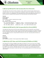
Page 36: ...tes the signal level at which the limit is to be activated The or sign indicates whether you want the limit to be activated when the signal is greater than the set point or less than the set point The latching should be set to 0 for latching off or 1 for latching on If latching on is selected the rest of the command may be omitted see example 2 Latching on will require a manual reset once the limi...

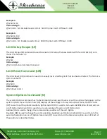
Page 37: ...latching limit that has been activated The format is L limit number R Example 123L1R Acknowledge 123 Reset Limit 1 System Options Command O The system Options command has 7 subcommands that are used to view or set the options that appear on the system options menu Option View OV displays all the settings in the system options menu Option Printer OP is used to set the printer baudrate Option Auto I...

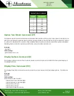
Page 38: ... 123 Com Baud Rate is 4800 Com Line Feed is off Retain Tare is off Option Printer Baudrate Command OP The Option Printer baudrate OP command is used to select the printer baudrate The format is OP code where the code is from the table shown at below Example 123OP9 Acknowledge 123 Printer Baud Rate is 230 4K Option Auto Identify Command OI The Option auto Identify OI command is used to turn auto id...

Page 39: ...te that valid addresses are 1 through 254 Example 123OA3 Acknowledge 003 Com Address is 003 Option Com Baudrate Command OB The Option com Baudrate OB command is used to change the communications baudrate for this unit The for mat is OB code where the baudrate codes are given in the table Code 7 is a special baudrate that is reserved for future expansion Note that the acknowledge is given at the cu...

Page 40: ... disable and 1 is enable Once enabled the tare values are retained until this option is disabled Disabling the tare retention option resets the tare values for both channels to 0 Example 123OT1 Acknowledge 123 Retain tare is on Display Options Command D The Display options command has 5 subcommands used to set options that effect the front panel display of the Model 4215 HS Display View Command DV...

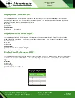
Page 41: ...ilter is Type I Level 3 Display Decimal Command DD The Display Decimal DD command sets the maximum number of decimal digits that are shown for Load Peak and Valley The format is DD channel number where channel is A or B and the number must be be tween zero and 5 Example 123DDA0 Acknowledge 123 Channel A shows 0 decimal digits Display Count by Command DC The Display Count by DC command sets the sma...

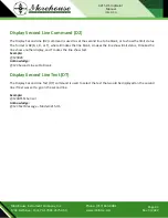
Page 42: ...the limit status The format is D2 B L D or T where B makes the line blank L makes the line show limit status D makes the line show another display and T makes the line show text Example 123D2B Acknowledge 123 Second Line set to Blank Display Second Line Text DT The Display Second Line Text DT command is used to select the text that would be displayed on the second line if text was set to go on the...

Page 43: ... attached Press any button to clear this display 4 You are now prompted to enter the first of two millivolt per volt references We recommend using 3 0 mv volt for the first and 3 0 mv volt for the second Set your reference and enter the appropriate number As soon as you press Enter the Model 4215 HS will start reading the reference 5 Next you are prompted for the second mv volt value Set your refe...

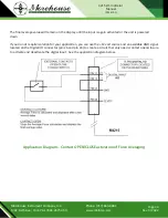
Page 44: ...put is again activated or the unit is powered down If you do not require isolation for your application you can use the 12 volt source and an available GND signal located on the Digital I O connector pin 26 and pin 24 to create a circuit that only needs contact open closure to activate and deactivate the digital input See the application diagram below Application Diagram Contact OPEN CLOSE activat...

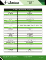
Page 45: ...2 of full scale Scaling Gain and offset selected by software Frequency Response Approx 15 Hz plus filtering Output Source Any displayed quantity Output Channels 1 std 2 optional Direct Analog Output Full Scale Output 8 14 VDC 0 25 VDC Linearity 0 02 of full scale Scaling Fixed with no tare transducer channel only Frequency Response Approx 1 5 kHz Peak Hold Peak Valley Hold Digital 1 60 second capt...

Page 46: ...s tare peak valley reset alternate view print Alternate functions for programming Digital Display Display Characters 2 lines by 20 characters Display Update 4 Sec Scaling Automatic or manual Maximum Display Count 999 999 Decimal Points Selection 0 to 5 software selectable Display Type Vacuum fluorescent Resolution 24 bit Software Filters 8 software selectable Electrical Characteristics Power Requi...

Page 47: ... are not used SENSE HI must be tied to EXCITE HI and SENSE LO must be tied to EXCITE LO Serial Port Connector DB9 Female Pin Signal 1 EXCITE HI 2 SENSE HI 1 3 CELL OUTPUT HI 4 CELL OUTPUT LO 5 SENSE LO 1 6 EXCITE LO 7 AUTO ID A 8 AUTO ID B 9 CHASSIS GND DB 15 Male Pin Signal 1 TXD 2 RXD 3 No Connect 4 SERIAL GND 5 TXD Printer 6 TXD Printer 7 RXD RS485 8 RXD RS485 9 No Connect 10 SERIAL GND 11 13 N...

Page 48: ...ectable using the Printer Baud entry on the System Options menu 3 Pins 7 8 14 and 15 are used for RS485 ASCII command set communications Use 8 data bits no parity 1 stop and set the baud rate using the Com Baudrate entry on the System Options menu Digital I O Connector High Density 26 Female Pin Signal 1 LIM 1 A 1 2 LIM 1 B 1 3 LIM 2 A 4 LIM 2 B 5 LIM 3 A 6 LIM 3 B 7 LIM 4 A 8 LIM 4 B 9 ISO IN 1 H...

Page 49: ...Model 4215 HS cannot be changed you cannot enter Setup mode 4 The encoder inputs are intended for use with a 12 VDC quadrature encoder For single ended signaling use the CHA and CHB pins the CHA L and CHB L pins are provided for differential signals The encoder can be supplied with the 12 VDC and GND available on pins 26 and 24 The Model 4215 HS will also accept 5 VDC encoder inputs but these MUST...

Page 50: ... 4101 Precision Shunt Calibration Resistors This diagram shows the connection of the precision internal shunt resistors The back panel switch shown to the left of the two resistors selects between 30 KΩ and 60 KΩ The shunt check relay shown to the right of the two resistors connects the selected resistor between the Excite High and the Cell Output High ...

Reviews: