32
The Interface Solution Experts
SPA
2
Programmable Current/Voltage
Limit Alarm Trips
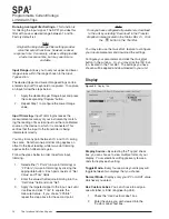
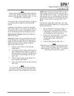
You may also use the
Quick Set feature to set these
features and download them. Simply click the
button in the Tool Bar.
6. SPA
2
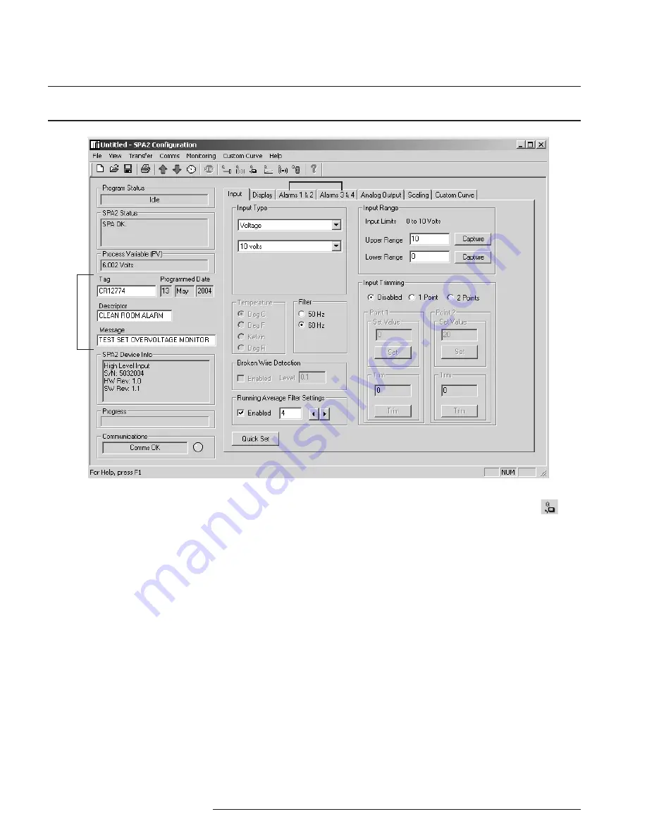
Device Info–
This “read-only” display indi-
cates instrument configuration, device identification,
hardware revision and software revision.
7.
Communications–
Notifies user of current PC
connection/communications status.
8. Input Tab–
Use this tab to set your input param-
eters. Refer to the
Input section for a complete
description.
9. Display Tab–
Used to set up the appearance of
the SPA
2
’s LCD screen. Refer to the
Display section
for a complete description.
10.
Alarms Tab (1 & 2 and 3 & 4)–
Alarm parameters
are configured using these windows. Alarms 1 & 2 are
located in the same window. Alarms 3 & 4 are
grouped together in another window. Refer to the
Alarms section for a complete description.
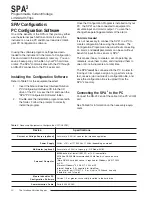
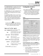
Figure 20.
SPA
2
(HLPRG) Main PC Screen
Once the default configuration has been saved to disk,
it is safe to program other parameters. The PC
Software is made up of these sections:
1. Tool Bar/Status Bar–
Dropdown menus and
corresponding icons allow you to perform various
functions throughout the PC Configuration Program.
Refer to the
Status and Tool Bar Legend for a com-
plete description.
2. Program Status–
This portion of the program
displays the activity of the connected unit. It will
display such messages as: Reading SPA Info, Idle,
Monitoring Variables and Monitor Fail.
3. SPA
2
Status–
Indicates if there are problems or
faults with the instrument.
4.
Process Variable (PV)–
Displays the selected
Process Variable.
5.
Identification Parameters–
Use this parameter to
place an identifying “Tag” (12 alphanumeric characters
max.), “Descriptor” (16 alphanumeric characters max.)
or “Message” (32 alphanumeric characters max.).
PC Configuration Software Summary
1
2
3
4
5
6
7
8
9
10
11
12
13

