The Interface Solution Experts 23
SPA
2
Programmable Current/Voltage
Limit Alarm Trips
Configuring the Alarm(s)
The SPA
2
offers you four alarms. Each of these
alarms may be configured as trip, fault or rate of
change alarms. The instructions below will explain the
steps to follow in order to set each type of alarm.
This section will be divided into three sub-sections:
“Trip Alarm Configuration”, “Fault Alarm Configuration”
and “Rate of Change Alarm Configuration”. Depending
upon the type of alarm you are setting, you may refer
to the section specific to your need at the time.
Trip Alarm Configuration
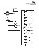
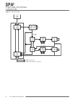
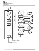
Figure 15 gives an overview of the Trip Alarm
Configuration menu.
Trip alarms are used if the user desires an alarm
condition if a process value deviates from a set trip
point.
1.
At the “CONFG ALARM” menu, press
SELECT. Use the UP and DOWN buttons to
toggle between the four alarms. When the
desired alarm appears, press
SELECT.
2.
At the “ALARM TYPE” menu press
SELECT.
From here you will choose your alarm type.
Use the
UP and DOWN buttons to scroll
through the selections. Press
SELECT once
“ALARM TRIP” is displayed.
3.
At “ENTER TRIP”, press
SELECT and enter
your alarm trip value. Use the
UP and DOWN
buttons to select your trip value; press
SELECT.
4.
Press
SELECT at “ENTER DBAND” and enter
your dead band value if using dead band.
Press
SELECT once your desired setting
appears.
Dead Band–
The Dead Band is the range
within which an alarm relay remains in an alarm
condition even after the monitored process
variable input has returned to a safe level, at or
below/above the trip point setting.
5.
Press
SELECT at “ENTER DELAY” and input
your desired delay time by using the
UP and
DOWN buttons.
Delay–
When your unit is in an alarm condition,
the delay is the amount of time you set
(0-120sec) to elapse before a relay trip.
6.
Pressing
SELECT at the “SET HI/LO” menu
directs you to configure the alarm as an
“ALARM HI” or “ALARM LO”. Use the
UP and
DOWN buttons to reach your selection and
press
SELECT.
ALARM LO–
You are notified if your process
input drops below your trip point setting.
ALARM HI–
You are notified if your process
input exceeds your trip point setting.
7.
At the “SET LATCH” display, press
SELECT
and choose “LATCH ON” or “LATCH OFF”
using the
UP and DOWN buttons; press
SELECT.
Latching Alarm–
When a SPA
2
is configured
with latching alarms, an alarm condition will not
“clear” (the relay will not change state) until the
input returns to a non-alarm state
AND
manual
reset terminals are shorted and then opened.
These manual reset terminals, labeled “MR” are
located on the top row of the SPA
2
.
8.
Press
SELECT at “SET FSAFE” to enter the
menu. Then use the
UP and DOWN buttons to
switch from “ALARM FSAFE” to “ALARM
NONFS”. Make your selection and press
SELECT.
Fail Safe (ALARM FSAFE)–
Will remain in an
alarm condition even if power to the unit is
removed. Its alarm trip relays are energized
whenever the process input is in a non-alarm
condition (including any dead band setting).
These relays de-energize when the process
input trips the alarm.
Non Fail Safe (ALARM NONFS)–
With this
type of alarm relays are energized whenever
the process input is in an alarm condition.
These relays de-energize when the process
input returns to the reset point (including any
dead band).

