


How To Adjust the Valve Preload
Chapter Seven: Troubleshooting
40
14. Slowly turn the adjustment nut while monitoring the DMM: clockwise rotation increases
the current required to open the valve; counterclockwise rotation decreases it. Adjust to
a target value of 25 mA.
Caution
Do not overturn the adjustment nut! Excessive turning may damage
the plug and cause poor closed conductance and flow control.
15. Holding the adjustment nut in place, re-tighten the jam nut. As you tighten the jam nut,
monitor the DMM to ensure that the current remains between 24 and 26 mA.
Tightening the jam nut tends to reduce the preload. It may be necessary to repeat the
adjustment and jam nut tightening to maintain proper values.
16. Change the set point input signal to 0.0 Volts.
17. Monitor the MFC output to verify that the valve closed conductance is within
specification.
Refer to Appendix A: Product Specifications, page 43, for the valve closed conductance
specification. If the valve fails to meet the closed conductance specification, return the
unit to MKS for service.
18. Change the inlet pressure to the minimum pressure expected during use.
19. Change the set point input signal to 5.0 Volts (100% full scale).
20. Observe the MFC output and control valve current. Record the valve current.
The MFC output should be 5.0 Volts (100%) and the valve current no greater than the
limits in Table 7. If the valve current exceeds these limits, return the unit to MKS for
service. If the valve current is less than or equal to the value in Table 7, it must be
adjusted.
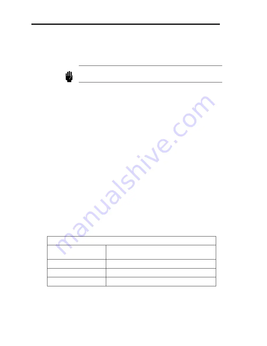
Maximum Valve Current
MFC Flow Capacity
(N2 equivalent)
Maximum Valve Current
(at 100% Set Point and Minimum Pressure)
≤
50 sccm
39 mA
100 to 500 sccm
45 mA
≥
1000 sccm
51 mA
Table 7: Maximum Valve Current
Summary of Contents for Mass-Flo 1479A
Page 3: ...119474 P1 Rev B 10 97 MKS Type 1479A Mass Flo Controller ...
Page 8: ...Table of Contents vi ...
Page 10: ...List of Figures and Tables viii ...
Page 34: ...Control Valve Chapter Three Overview 24 This page intentionally left blank ...
Page 40: ...The Optional Input Chapter Four Operation 30 This page intentionally left blank ...
Page 44: ...Zero Adjustment Chapter Six Maintenance 34 This page intentionally left blank ...
Page 70: ...Model Code Appendix D Model Code 60 This page intentionally left blank ...