MKS Mass-Flo 1479A Instruction Manual Download Page 48

How To Adjust the Valve Preload

Chapter Seven:  Troubleshooting

38

1. Set your processing system to supply the MFC with a non-hazardous gas (Ar, N

2

, or He)

and purge thoroughly.

Warning

You MUST use a “safe” gas while making any valve
adjustments to safeguard against inadvertent exposure to
any toxic or hazardous gas.  DO NOT adjust the valve while a
hazardous or toxic gas is flowing through the MFC.

If you cannot use a “safe” gas within your processing system, remove the MFC and
purge the unit as required by your corporate policies and any appropriate safety
procedures.

2. Disconnect the cable to power down the unit and remove the unit from the process tool.

3. Connect the inlet of the unit to the gas supply and adjust the pressure to the maximum

level used on the process tool.

Choose a “safe” gas with a similar molecular weight as the actual process gas.  More
specifically, helium is best used as a substitute for other very light gases such as
hydrogen.

4. Use a 

3

/

32

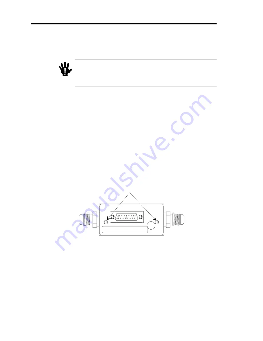
” allen wrench to remove the enclosure retaining screws.  Remove the enclosure

cover.

Figure 8 shows the location of the retaining screws.

Enclosure Retaining Screws

Figure 8:  Location of the Retaining Screws

5. Disconnect the leads from the control valve to the PC board.

6. Remove the two (2) 4-40 socket head cap screws and the two (2) 2-56 Phillips head

screws (holding the PC brackets).  Gently lay the bracket/PC board assembly on the
bench top.

Handle the unit carefully to avoid damaging the flex print that connects the sensor and
the main PC board.

Summary of Contents for Mass-Flo 1479A

Page 1: ... P1 Rev B 10 97 Instruction Manual MKS Type 1479A Mass Flo Controller Six Shattuck Road Andover MA 01810 2449 800 227 8766 or 978 975 2350 Fax 978 975 0093 E mail mks mksinst com Web site http www mksinst com ...

Page 2: ...S of this warranty The purchaser before returning any equipment covered by this warranty which is asserted to be defective by the purchaser shall make specific written arrange ments with respect to the responsibility for shipping the equipment and handling any other incidental charges with the MKS sales representative or distributor from which the equipment was purchased or in the case of a direct...

Page 3: ...119474 P1 Rev B 10 97 MKS Type 1479A Mass Flo Controller ...

Page 4: ...demark of MKS Instruments Inc Andover MA Cajon VCR and VCO are registered trademarks of Cajon Company Macedonia OH Teflon is a registered trademark of E I DuPont de Nemours and Co Inc Wilmington DE Kalrez and Viton are registered trademarks of DuPont Dow Elastomers Wilmington DE Swagelok and NUPRO are registered trademarks of Crawford Fitting Company Solon OH Kel F is a registered trademark of 3M ...

Page 5: ...ganized 7 Customer Support 8 Chapter Two Installation 9 How To Unpack the Type 1479 Controller 9 Opening the Package 9 Unpacking Checklist 10 Environmental Requirements 10 Setup 11 Dimensions 12 Gas Line Connections 13 Standard Fittings 13 Optional Fittings 13 Mounting a Type 1479 MFC 13 The Type 2479 MFC 15 Mounting a Type 2479 MFC 15 Interface Cables 16 Generic Shielded Cable Description 17 Exam...

Page 6: ...28 Priority of the Commands 28 The Optional Input 29 Chapter Five Theory of Operation 31 Flow Path 31 Measurement Technique 31 Control Circuitry 32 Chapter Six Maintenance 33 General 33 Zero Adjustment 33 Chapter Seven Troubleshooting 35 Troubleshooting 35 How To Adjust the Valve Preload 37 Appendix A Product Specifications 43 Performance Specifications 43 Environmental Specifications 44 Electrica...

Page 7: ...Table of Contents v How To Determine the Flow Controller Range 52 How To Determine the Valve Configuration 53 Appendix D Model Code 57 Model Code 57 Index 61 ...

Page 8: ...Table of Contents vi ...

Page 9: ... Alternate Method To Use When Cable Clamp is Not Available 18 Figure 8 Location of the Retaining Screws 38 Figure 9 Location of the Jam Nut and Adjustment Nut 39 Figure 10 The PC Board 41 Tables Table 1 Definition of Symbols Found on the Unit 2 Table 2 MKS Interface Cables 16 Table 3 9 Pin Type D Connector Pinout 19 Table 4 15 Pin Type D Connector Pinout 20 Table 5 20 Pin Edge Card Connector Pinou...

Page 10: ...List of Figures and Tables viii ...

Page 11: ...ice condition or the like which if not correctly performed or adhered to could result in injury to personnel Caution The CAUTION sign denotes a hazard to equipment It calls attention to an operating procedure practice or the like which if not correctly performed or adhered to could result in damage to or destruction of all or part of the product Note The NOTE sign denotes important information It ...

Page 12: ... IEC 417 No 5019 Frame or chassis IEC 417 No 5020 Equipotentiality IEC 417 No 5021 Direct current IEC 417 No 5031 Alternating current IEC 417 No 5032 Both direct and alternating current IEC 417 No 5033 a Class ll equipment IEC 417 No 5172 a Three phase alternating current IEC 617 2 No 020206 Caution refer to accompanying documents ISO 3864 No B 3 1 Caution risk of electric shock ISO 3864 No B 3 6 ...

Page 13: ...service must be made by qualified service personnel only USE CAUTION WHEN OPERATING WITH HAZARDOUS MATERIALS If hazardous materials are used observe the proper safety precautions completely purge the instrument when necessary and ensure that the material used is compatible with the wetted materials in this product including any sealing materials PURGE THE INSTRUMENT After installing the unit or be...

Page 14: ...surized gas source install a suitable burst disc in the vacuum system to prevent system explosion should the system pressure rise KEEP THE UNIT FREE OF CONTAMINANTS Do not allow contaminants to enter the unit before or during use Contamination such as dust dirt lint glass chips and metal chips may permanently damage the unit or contaminate the process ALLOW THE UNIT TO WARM UP If the unit is used ...

Page 15: ...s not supply power the 660 unit can be used as a power supply and readout though it cannot send a set point to the flow controller Refer to the corresponding manuals for requirements and instructions The 1479 flow controller is available in a variety of types and configurations to suit specific needs The options that must be specified when you order the flow controller include Connector Type D con...

Page 16: ...rnal seals thus eliminating elastomeric seals which are a key source of particle generation outgassing and permeation The metal seal also ensures extremely low external leakage The internal valve control plug is Teflon or Kel F depending on flow range or Kel F depending on flow range which further reduces outgassing and particle generation The 1479A mechanical design minimizes wetted surface area ...

Page 17: ...n how to use a Gas Correction Factor when interpreting the output signal for a gas other than the calibration gas Chapter Four Operation explains how to start up and operate the mass flow controller It also discusses how to override the control valve Chapter Five Theory of Operation provides additional information on how the flow controller operates Chapter Six Maintenance lists a few general prac...

Page 18: ...n the use of your Type 1479 instrument or to obtain information about companion products MKS offers contact any authorized MKS Calibration and Service Center If it is necessary to return the instrument to MKS please obtain an ERA Number Equipment Return Authorization Number from the MKS Calibration and Service Center before shipping The ERA Number expedites handling and ensures proper servicing of...

Page 19: ...he unit to MKS obtain an ERA Number Equipment Return Authorization Number from the MKS Service Center before shipping Please refer to the inside of the back cover of this manual for a list of MKS Calibration and Service Centers Opening the Package The 1479 controller is assembled leak tested with helium and calibrated in a clean room environment The instrument is double bagged in this environment ...

Page 20: ...Observe the pressure limits A Maximum gas inlet pressure is 250 psig B Operational differential pressure is 10 to 40 psid for 5000 sccm units 15 to 40 psid for 10 000 and 20 000 sccm units The standard valve configuration provides control over this range with the outlet at atmospheric pressure 3 Provide power input at 15 VDC 5 200 mA A Maximum voltage current at startup is 15 VDC 5 200 mA B Typica...

Page 21: ...roller page 26 2 Install the flow controller in the gas stream such that the flow will be in the direction of the arrow on the side of the controller 3 Allow adequate clearance for the cable connector and tubing Straight Shielded connectors require approximately 3 76 2 mm height Right Angle connectors require approximately 2 50 8 mm height 4 Position the flow controller to provide access to the ze...

Page 22: ... 139 5 with Type D connector 5 30 134 6 with recessed P C Edge Board connector or 0 50 12 7 3 00 76 2 Figure 1 Outline Dimensions of the 1479 Flow Controller Note The method used to measure the overall length of the unit varies with the type of fitting For VCR compatible fittings the unit is measured from mating face to mating face For Swagelok compatible fittings the unit is measured from fitting...

Page 23: ...stream tubing Standard Fittings The 1479 flow controller is equipped with Cajon 4 VCR male compatible fittings For specific information regarding these fittings refer to the manufacturer s documentation Optional Fittings As an option inch Swagelok compatible or inch weld stubs are available when specified Mounting a Type 1479 MFC Tapped holes are provided in the base of the unit for mounting Refer...

Page 24: ...Mounting a Type 1479 MFC Chapter Two Installation 14 2 75 69 9 0 13 3 2 0 35 8 9 0 38 9 5 2 25 57 2 0 75 19 1 8 32 UNC 2B x 0 25 DP 4 places Figure 3 Mounting Dimensions of the 1479 Flow Controller ...

Page 25: ...P1 is attached to the unit to secure it in place and make it a drop in replacement for other MKS MFCs with close coupled shutoff valves Mounting a Type 2479 MFC Mount each assembly horizontally if possible Placement of flow components in a different orientation may cause a small zero shift The zero offset can be removed according to the instructions in How To Zero the Flow Controller page 26 Refer...

Page 26: ... or flying leads are not CE Mark compliant MKS offers a variety of interface cables listed in Table 2 Note 1 An overall metal braided shielded cable properly grounded at both ends is required to meet CE Mark specifications 2 To order an overall metal braided shielded cable add an S after the cable type designation For example to order a standard connection cable to connect the 1479 MFC to a power ...

Page 27: ...uffice 4 For shielded cables with flying leads at one or both ends it is important at each such end to ground the shield before the wires exit Make this ground with absolute minimum length Refer to Figures 6 and 7 page 18 A inch piece of 22 wire may be undesirably long since it has approximately 5 nH of inductance equivalent to 31 ohms at 1000 MHz After picking up the braid s ground keep wires and...

Page 28: ...Washer External Tooth Lock Washer Transducer Housing Optional Plastic or Metal Cable Clamp For Physical Strain Relief Figure 6 Preferred Method Example 2 Alternate Method To Connect Cable shown on a pressure transducer Transducer Overall Insulation if present Braid Strands Twisted Under Washer Keep Wires Flat Against Case Optional Plastic or Metal Cable Clamp For Physical Strain Relief Screw Split...

Page 29: ...ns connector 9 Pin Type D Connector Table 4 lists the pinout of the 9 pin Type D connector for the 1479 mass flow controller 9 Pin Type D Connector Pinout Pin Number Assignment 1 Valve Open Close 2 Signal Output 3 15 V 4 Power Common 5 15 V 6 Set Point Input 7 Signal Common 8 Signal Common 9 MKS Test Point Table 3 9 Pin Type D Connector Pinout Note 1 Chassis ground is not available on a separate p...

Page 30: ...al Common 4 Valve Open TTL low 12 Signal Common 5 Power Supply Common 13 No Connection 6 15 VDC 14 No Connection 7 15 VDC 15 Chassis Ground 8 Set Point Input 0 to 5 VDC Table 4 15 Pin Type D Connector Pinout Note 1 The No Connection pin assignment refers to a pin with no internal connection 2 The 0 to 5 VDC flow signal output comes from pin 2 and is referenced to pin 12 signal common 3 Any appropr...

Page 31: ...5 VDC 7 Key H Key 8 No Connection J MKS Test Point 9 No Connection K No Connection 10 Signal Common L Valve Close TTL low Table 5 20 Pin Edge Card Connector Pinout Note 1 The No Connection pin assignment refers to a pin with no internal connection 2 Pins 1 through 10 are located on one side of the gold finger connection and pins A through L are located on the opposite side of the gold finger conne...

Page 32: ...using is not listed in the appendix you must calculate its GCF using the following equation GCF 0 3106 S d Cp x x x where GCFx Gas Correction Factor for gas X dx Standard Density of gas X g l at 0 C and 760 mmHg Cpx Specific Heat of gas X cal g C 0 3106 Standard Density of nitrogen Specific heat of nitrogen S Molecular Structure correction factor where S equals 1 030 for Monatomic gases 1 000 for ...

Page 33: ...ich the armature moving valve mechanism is suspended by two springs This arrangement ensures that no friction is present and makes precise control possible The 1479 controller has the valve normally closed the control current is used to lift the armature and plug assembly from the seat allowing a controlled flow of gas ...

Page 34: ...Control Valve Chapter Three Overview 24 This page intentionally left blank ...

Page 35: ...wer supply readout unit 3 Apply power to the MFC instrument When power is first applied the output signal jumps to approximately 7 0 VDC You can monitor the flow output signal as the heaters stabilize and the output approaches zero Approximately 2 minutes after power up the output signal should be within 10 mV 0 2 F S of the final voltage at all specified flow rates Warning If the instrument is be...

Page 36: ...pressure equalizes across the flow controller Note A set point command signal greater than 50 mV 1 of full scale is required for the flow controller to generate an output Adjust the Zero Pot 1 Once flow through the controller has stopped reached zero flow and stabilized remove the set point or valve open command 2 Turn the Zero pot located on the inlet end of the flow controller until the readout ...

Page 37: ...ler Refer to Figure 1 page 12 for the location of the gain pot To decrease flow signal oscillation Turn the controller gain counter clockwise to decrease the controller gain setting Note Lowering the supply pressure to the MFC will have the same effect as decreasing the gain since it will reduce the overflow underflow effect of the valve To increase MFC response to a change in set point Increase t...

Page 38: ...signal to pin 1 To close the valve apply ground to pin 1 Note To control with a TTL signal use a tri stated device If the 1479 flow controller is equipped with an Edge Card connector To open the valve apply a TTL low to pin D or connect pin D to signal ground pin 10 To close the valve apply a TTL low to pin L or connect pin L to signal ground pin 10 Priority of the Commands The 1479 flow controlle...

Page 39: ...Edge Card Connector For the connector pinouts refer to Table 4 page 20 and Table 5 page 21 respectively Note The 9 pin Type D connector does not support the optional input feature This feature is only available on the 15 pin Type D and Edge Card connectors Voltage applied to the optional input pin overrides the signal generated by the flow sensor internal to the 1479 unit The control electronics d...

Page 40: ...The Optional Input Chapter Four Operation 30 This page intentionally left blank ...

Page 41: ...one of the following A sensor tube for ranges 10 sccm N2 equivalent A sensor tube and parallel bypass for ranges 10 sccm N2 equivalent The geometry of the sensor tube in conjunction with the specified full scale flow rate ensures fully developed laminar flow in the sensing region The bypass elements are specifically matched to the characteristics of the sensor tube to achieve a laminar flow splitt...

Page 42: ...roller accepts a 0 to 5 VDC set point signal compares it to its own flow signal and generates an error voltage This error signal is then conditioned by a PID Proportional Integral Derivative algorithm and amplified so that it can reposition the control valve thus reducing the control error to zero Since the control valve is normally closed the 1479 unit lifts the armature and plug assembly from th...

Page 43: ... controller Note If it is necessary to return the instrument to MKS for repair please contact any of the MKS international service calibration centers listed on the inside of the back cover of this manual for an ERA Equipment Return Authorization number to expedite handling and ensure proper servicing of your instrument Zero Adjustment For best accuracy and repeatability you should check the zero ...

Page 44: ...Zero Adjustment Chapter Six Maintenance 34 This page intentionally left blank ...

Page 45: ...n proper flow direction Controller does not track set point Improper zero adjustment Zero meter output according to How To Zero the Flow Controller page 26 Controller does not function Electronics malfunctioning Return for service Oscillation Too high a controller gain setting Incorrect upstream pressure regulator Upstream pressure too high Excessive valve preload Reduce turn counter clockwise Che...

Page 46: ...Possible Cause Remedy Unit does not achieve full flow Upstream pressure too low Excessive valve preload Incorrect maximum valve current setting Increase upstream pressure Readjust the valve according to How To Adjust the Valve Preload page 37 Return for service Table 6 Troubleshooting Chart ...

Page 47: ...all highly sensitive precision electronic instruments Note Valve preload adjustment cannot be performed in situ because the procedure involves disassembling the MFC Perform this procedure on a properly equipped workbench This procedure requires the following equipment Any special safety equipment necessary to handle the gas in use 3 32 allen wrench for the enclosure retaining and bracket hold down...

Page 48: ...ol 3 Connect the inlet of the unit to the gas supply and adjust the pressure to the maximum level used on the process tool Choose a safe gas with a similar molecular weight as the actual process gas More specifically helium is best used as a substitute for other very light gases such as hydrogen 4 Use a 3 32 allen wrench to remove the enclosure retaining screws Remove the enclosure cover Figure 8 ...

Page 49: ... Zero the unit following the instructions in How To Zero the Flow Controller page 26 10 Reconnect one electrical valve lead to a post on the PC Control board via a short clip lead and the other via a DMM in series The leads are interchangeable Set the DMM to measure current in the 10 to 100 mA range 11 Open all upstream and downstream isolation valves in the system 12 Hold the valve adjustment nut...

Page 50: ...nitor the MFC output to verify that the valve closed conductance is within specification Refer to Appendix A Product Specifications page 43 for the valve closed conductance specification If the valve fails to meet the closed conductance specification return the unit to MKS for service 18 Change the inlet pressure to the minimum pressure expected during use 19 Change the set point input signal to 5...

Page 51: ...urrent Limiting potentiometer R85 on the PC board The potentiometer R85 is located in the top right hand corner of the PC board It is the only black potentiometer on the board and is much smaller than the other potentiometers Valve Current Limit Potentiometer Figure 10 The PC Board ...

Page 52: ...rent Headroom 23 Provide a 5 Volt set point signal 24 Turn off the gas supply 25 When the flow output has dropped to zero adjust the Current Limiting potentiometer R85 until the required valve current limit is obtained Note that counter clockwise rotation increases the maximum current while clockwise rotation decreases it 26 Remove the DMM and reconnect the valve lead 27 Re install the brackets an...

Page 53: ...ational differential pressure4 5000 sccm 10 000 to 20 000 sccm 10 to 40 psid 15 to 40 psid Pressure coefficient 0 02 Rdg psi Repeatability 0 2 F S Resolution measurement 0 1 F S Temperature coefficients Zero Span 0 05 F S C 500 ppm 0 08 of Rdg C 800 ppm Warm up time to within 0 2 of steady state 2 minutes 1Includes non linearity hysteresis and non repeatability referenced to 760 mmHg and 0 C 2 An ...

Page 54: ...mperature 20 to 65 C 4 to 149 F Electrical Specifications CE Mark Compliance EMC Directive 89 336 EEC Input voltage Current required Max at start up first 5 seconds 5 Typical at steady state 15 VDC 5 200 mA 15 VDC 5 100 mA Output impedance 1 ohm Output signal minimum load 0 to 5 VDC into 10K ohm Set point command signal controllers only 0 to 5 VDC from 20K ohm 5Add 100 mA to start up current if th...

Page 55: ...e Swagelok compatible or tube weld stubs Internal surface area 500 sccm unit 7 7 in2 49 7 cm2 Internal volume 500 sccm unit 0 27 in3 4 43 cm3 Leak integrity External scc sec He Through closed valve 1 x 10 10 1 0 F S 40 psi Materials wetted Body Seals Valve Seat 316L VAR SST 316L SST nickel Metal Kel F Teflon Maximum inlet pressure 250 psig Surface Finish 16 µinches Ra electropolished Weight 1 9 lb...

Page 56: ...Physical Specifications Appendix A Product Specifications 46 This page intentionally left blank ...

Page 57: ...2 CO CCl4 CF4 Cl2 0 2016 0 2488 0 1655 0 1654 0 1144 1 964 1 250 6 86 3 926 3 163 0 701 1 00 0 31 0 42 0 86 Chlorodifluoromethane Freon 22 Chloropentafluoroethane Freon 115 Chlorotrifluoromethane Freon 13 Cyanogen Deuterium CHClF2 C2 ClF5 CClF3 C2 N2 D2 0 1544 0 164 0 153 0 2613 1 722 3 858 6 892 4 660 2 322 0 1799 0 46 0 24 0 38 0 61 1 00 Diborane Dibromodifluoromethane B2 H6 CBr2 F2 0 508 0 15 1...

Page 58: ...3 0 176 0 1357 0 1432 0 153 1 695 3 127 6 129 5 395 4 660 0 98 0 50 0 33 0 35 0 38 Freon 13 B1 Freon 14 Freon 21 Freon 22 Freon 23 CBrF3 CF4 CHCl2 F CHClF2 CHF3 0 1113 0 1654 0 140 0 1544 0 176 6 644 3 926 4 592 3 858 3 127 0 37 0 42 0 42 0 46 0 50 Freon 113 Freon 114 Freon 115 Freon 116 Freon C318 C2 Cl3 F3 C2 Cl2 F4 C2 ClF5 C2 F6 C4 F8 0 161 0 160 0 164 0 1843 0 1866 8 360 7 626 6 892 6 157 8 93...

Page 59: ...339 1 250 0 56 0 21 1 46 0 99 1 00 Nitrogen Dioxide Nitrogen Trifluoride Nitrous Oxide Octafluorocyclobutane Freon C318 Oxygen NO2 NF3 N2 O C4 F8 O2 0 1933 0 1797 0 2088 0 1866 0 2193 2 052 3 168 1 964 8 93 1 427 2 0 48 0 71 0 164 1 00 Pentane Perfluoropropane Phosgene Phosphine Propane C5 H12 C3 F8 COCl2 PH3 C3 H8 0 398 0 194 0 1394 0 2374 0 3885 3 219 8 388 4 418 1 517 1 967 0 21 0 17 0 44 0 76 ...

Page 60: ...o 1 2 2 Trifluoroethane Freon 113 Tungsten Hexafluoride Xenon SF6 CCl3 F SiHCl3 CCl2 FCClF2 or C2 Cl3 F3 WF6 Xe 0 1592 0 1357 0 1380 0 161 0 0810 0 0378 6 516 6 129 6 043 8 360 13 28 5 858 0 26 0 33 0 33 0 20 0 25 1 32 1 Empirically defined 2 Consult MKS Instruments Inc for special applications NOTE Standard Pressure is defined as 760 mmHg 14 7 psia Standard Temperature is defined as 0oC ...

Page 61: ...gas correction factor for the gas to be used MKS states the flow controller ranges based on flow rate of nitrogen the flow rate for other gases may vary The proper valve configuration depends upon the flow range inlet pressure differential pressure across the unit and density of the gas Proper valve configurations have been established for all standard flow ranges flowing nitrogen under standard o...

Page 62: ...on Factors page 47 The GCF for Ar is 1 39 2 Insert the GCF of Ar in the following formula GCF of N2 GCF of Ar x Desired flow rate of Ar where x is the equivalent flow rate of nitrogen sccm 1 00 1 39 x 250 sccm Ar x 180 sccm N2 A flow rate of 250 sccm of Ar will produce a flow rate equivalent to 180 sccm of N2 This falls within the range of a 200 sccm flow controller When calculating equivalent N2 ...

Page 63: ... 0 303 215 0 036 0 039 0 045 0 054 0 062 0 076 0 107 0 168 0 238 0 336 165 0 042 0 046 0 052 0 063 0 072 0 087 0 122 0 192 0 272 0 384 150 0 044 0 048 0 055 0 066 0 075 0 092 0 128 0 202 0 285 0 403 125 0 049 0 054 0 061 0 073 0 083 0 101 0 141 0 221 0 312 0 441 100 0 058 0 062 0 069 0 082 0 094 0 113 0 158 0 248 0 349 0 493 75 0 077 0 077 0 082 0 097 0 110 0 132 0 183 0 286 0 404 0 570 50 0 116 0...

Page 64: ...m flow rate for the unit Choose the valve configuration above your calculated Cv value to ensure that the unit can deliver the required flow Valve Configuration Selection Guide Valve Configuration Nominal Range N2 sccm Cv x 10 5 1 10 2 44 2 20 4 88 3 50 12 21 4 100 24 42 5 200 48 84 6 500 122 11 7 1000 244 22 8 2000 488 44 9 5000 1221 11 10 10000 1924 47 11 20000 3848 94 12 30000 5773 41 Table 10 ...

Page 65: ... 53 The Gas Density for boron trichloride listed in Appendix B Gas Correction Factors page 47 is 5 227 The Cv Pressure Factor read from Table 9 page 53 for a 20 psia inlet and 5 psid differential pressure is 0 373 Therefore our equation becomes CV max 250 sccm 1 293 5 227 0 373 Cv 187 5 2 Select the valve configuration with a Cv value that is closest to though larger than the Cv value calculated i...

Page 66: ...How To Determine the Valve Configuration Appendix C MFC Sizing Guidelines 56 This page intentionally left blank ...

Page 67: ...ith the flow control valve in a normally closed configuration The desired options are identified in the model code when you order the unit The model code is identified as follows 1479AXXXY1WZ where Type Number Full Scale Range Fittings Connector Seals 1 Z W XXX Y 1479A Valve Type Number 1479A This designates the model number of the instrument The mass flow controller is identified as the Type 1479...

Page 68: ... 50 51C 100 12C 200 22C 500 52C 1 000 13C 2 000 23C 5 000 53C 10 000 14C 20 000 24C Fittings Y Three types of fittings are available designated by a single letter code Ordering Code Cajon 4 VCR Male R Swagelok tube S tube weld stub A Valve 1 The valve configuration is designated by a single number code Ordering Code Normally Closed 1 Normally Open 2 Consult factory for availability ...

Page 69: ...rd C Digital RS 485 5 Digital DeviceNet 6 Consult factory for availability Seals Z The all metal seals are indicated by a single letter code Ordering Code All metal M How To Order a Mass Flow Controller To order the Type 1479 MFC with a 500 sccm full scale range Cajon 4 VCR fittings a normally closed valve 15 pin Type D connector and an all metal seal the product code is 1479A 52C R 1 B M ...

Page 70: ...Model Code Appendix D Model Code 60 This page intentionally left blank ...

Page 71: ...ttings 13 Flow path 31 G Gas connections 13 Gas correction factor 22 47 I Interface cables 16 Interface connectors 16 Introduction 5 L Leak rate 15 M Maintenance 33 Manual organization 7 Measurement technique 31 Mounting 13 N NUPRO valve 15 P Performance specifications 43 Physical specifications 45 PID control 32 Power requirements 10 Product code 5 57 R Reliability 6 Repair 33 Returns 8 9 S Set p...

Page 72: ...Index 62 T Troubleshooting 35 U Unpacking 9 checklist 10 opening 9 V Valve override 28 Z Zero 26 ...

Reviews: