UNIFORMITY DATA TRANSFER
- 10 -
1. Outline
After replacing the LCD block, you can correct some color
uniformity by transferring the uniformity data.
Note:
When replacing the LCD block and the PCB MAIN
ASSY at the same time, be sure to transfer the
factory adjustment data referring to “REPLACEMENT
OF THE MAIN PCB ASSY.”
2. Preparation
The CV-C300 (Data Trans) program runs on Microsoft
®
Windows
®
95/98. Use a PC with Windows
®
95/98 installed.
1. Load the CD-ROM into the CD drive and select CD drive.
2. Double-click the “Uniformity Data Transmit” folder.
3. Double-click the “English” folder.
4. Double-click the “setup.exe.” folder and install (set up) it.
Note:
Select C:\CV-C300\ as the directory for installation
(set up).
5. Copy the transfer data folder containing the transfer data
files (.csv files) to the PC.
3. Operation
(1) Connection
Connect the PC with the projector using the attached RS-
232C cable.
(2) Starting Uniformity Data Transfer
Double-click the CV-C300(Data Trans).exe file in the CV-
C300 folder in the C drive to start the program.
(You can also start the program by clicking the “Start” button
by selecting “Program” in the Start menu and clicking “CV-
C300 Data Transfer Software.”)
(3) Main dialog window
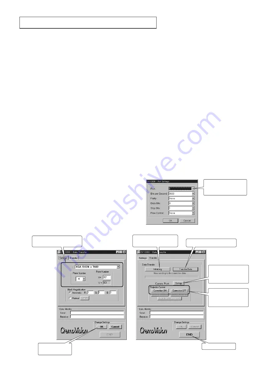
1. Start the CV-C300 (Data Trans).exe program to display
the main dialog window.
2. Select the “Settings” tag of the main dialog and set the
“Resolution, Plane Number, Point Number” for the model
to which the data are transferred as shown below. After
completing setting, click “OK” in the “Change Settings”
field to save the settings. When you change the settings,
also click “OK.”
3. Select the “Transfer” tag in the main dialog. Click the
“Transfer Data” button and select the data transfer folder,
which has been copied to the PC in step 4 of
“2. Preparation” to display the data transfer files. Select
one file that contains data you want to transfer, and
double-click the file or click the “Open” button. (There
are several types of data transfer files.) When you
select one file, transfer of the data will start.
4. When an error message is displayed and data transfer
stops in the middle of transfer, switch the COM port and
start transferring the data again. (Refer to (4) Switching
the COM port.)
5. When the window showing that transfer has been
completed is displayed, correction of uneven colors
takes effect. Switch “Correction ON” and “Correction
OFF” of Projector Control in the main dialog to check the
results of the correction.
6. There are several types of data provided for color check.
Check the results with each data and then transfer the
optimum data again.
(4) Switching the COM port
1. Select the serial port to which the cable is being
connected.
2. Press the “OK” button to switch the COM port.
Selects the COM port.
Do not change other
settings.
COM port switching dialog window
Main dialog window
Switch ON and OFF
after transferring data to
check the result of the
correction.
Select depending on the model
to which the data are transferred.
Switches the COM port
when communication
with the PC is not
available.
Saves the changed
settings.
Selects data to be transferred.
Transfers the data with no
correction (all 0 data).
Exits the application.
Settings
Transfer
XL2U
Resolution
: XGA
Plane No.
: 4
Point No.
: X=17
Y=13
SL2U
Resolution
: SVGA
Plane No.
: 4
Point No.
: X=17
Y=13
(When you enter 17
for X, Y is
automatically set to
13.)


