3-34
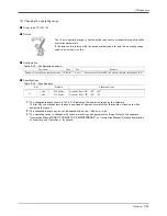
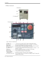
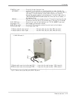
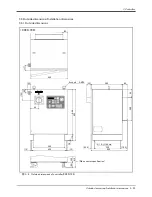
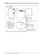
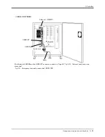
Names of each part
3 Controller
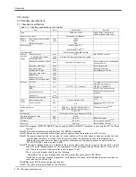
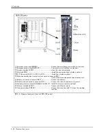
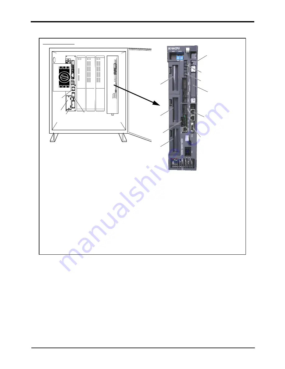
図 3-3 : Names of each part (interior CR3D-700 series)
①
②
④
③
⑤SLOT1
⑥SLOT2
⑦SLOT3
R700CPUユニット
OPT1
(予約済)
⑩OPT2
⑪MEMORY CASSETTE
⑫LAN1
⑬CNENC
⑨BAT
⑧RIO
① Emergency stop input(EMGIN)........................................... Connect the emergency stop switch to the robot.
② Emergency stop output(EMGOUT) .................................. The robot's error condition is outputted.
③ Special stop input(SKIP)....................................................... stops the robot immediately.
④ Hand slot(HND)......................................................................... Install the pneumatic hand interface optional.
⑤⑥⑦ Option slot(SLOT1, SLOT2, SLOT3)..................... Install the interface optional.
⑧ Extension parallel input/output unit connection connector(RIO)
Connect the extension parallel input/output unit.
⑨ Battery connection connector(BAT)............................... Connect the battery
⑩ Addition axis connection connector(OPT).................... Connect the cable for addition axis control.
⑪ Expansion memory cassette(
MEMORY CASSETTE
).... Install the memory cassette optional.
⑫ Ethernet interface(LAN1)..................................................... Connect the Ethernet cable.
⑬ Tracking interface(CNENC)................................................. Connect the encoder cable, if it uses the tracking
function.
CR3D-700 series

