6Safety
Safety 6-97
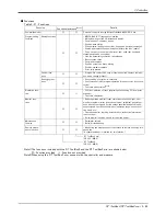
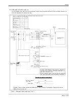
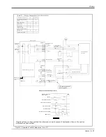
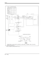
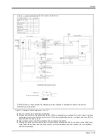
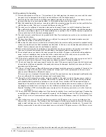
Fig.6-3 : Example of safety measures (
Case
3 )
1A/1B
2A/2B
3A/3B
4A/4B
5A/5B
6A/6B
8A/8B
9A/9B
1A/1B
2A/2B
3A/3B
4A/4B
10A/10B
11A/11B
5A/5B
6A/6B
EMGIN1/2
EMGIN1/2
EMGOUT1/2
EMGOUT1/2
}
Enabling device
Enabling device switch
The enabling switch of
the user jog box
Mode
TB servo on operation
TB enable switch
Enabling device
IO/OP servo on operation
Robot servo
EMG
Teach
Auto
Close
Open
ON
Close
Close
Open
Open
ON
ON
ON
RA
RA
RA
RA
RA
RA
RA
Robot controller
OP emergency
stop button
TB emergency
stop button
External emergency
stop input
Short
Short
system emergency
stop output
Constitute by customer
Internal emergency
stop circuit
Door
Door switch
output
Enabling device input
Mode output
Error output
→Include S/W
emergency stop
Door switch input
Internal emergency stop circuit
Additional axis
contactor
control
output
Example of customer wiring (case 3)
System emergency
stop output
Door switch output
Time chart
<Case 3 > : Use the mode output of the robot controller.
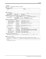
Emergency stop input
I/O
Connection
External emergency stop
input
I
○
Door switch input
I
○
Enable input
I
○
Error output
O
Additional axes
contactor control output
O
Mode output
O
○
External relay wiring
[Caution] Since we have omitted the information in part because of explanation, there is the section
different from the product.

