CHASSIS ELECTRICAL ±
Multi-Center Display <High Grade>
54A-103
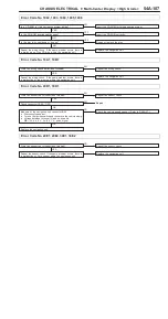
INSPECTION PROCEDURE 8
Display moves about.
Screen colors do not match correctly.
OK
Replace the DIN connector.
Check connectors:
C-50, C-52, C-53, C-54 and DIN connectors
between navigation unit and audio unit
NG
Repair
OK
Do red, blue and green colors appear in the monitor color bar
service function?
YES
End (no abnormality)
NO
Check the RGB wave pattern at terminal (1) of the C-53 multi-center
display harness-side connector.
OK
Replace the multi-center display unit.
NG
Check the RGB wave pattern at terminal (24) of the C-54 audio
unit harness-side connector.
OK
Check the harness between B-09 and B-04, and repair if necessary.
NG
Check the RGB wave pattern at the DIN connector at the audio
unit side of the cable between the audio unit and the navigation
unit.
OK
Replace the audio unit.
NG
Check the RGB wave pattern at the DIN connector at the navigation
unit side of the cable between the audio unit and the navigation
unit.
NG
Replace the navigation unit.
INSPECTION PROCEDURE 9
Daytime/nighttime display mode does not change in conjunction with lighting switch operations.
Check connector:
C-52
NG
Repair
OK
Carry out a vehicle signal check (service function).
Does LIGHT SW: ON appear when the lighting switch is ON,
and LIGHT SW: OFF appear when the lighting switch is off?
YES
End
NO
Measure at the C-52 multi-center display unit connector.
D
Connector connected
D
Voltage between terminal (24) and body ground
OK:Hi:
10 V or higher,
Lo:
0 ± 1 V
OK
Replace the multi-center display unit.
NG
Check the harnesses between the multi-center display unit and
the ETACS-ECU <vehicles with DRL> or front-ECU (tail lamp
relay) <vehicles without DRL >, and replace if necessary.
Summary of Contents for Pajero Pinin 1999
Page 32: ...NOTES ...
Page 73: ...13A 1 FUEL CONTENTS GASOLINE DIRECT INJECTION GDI 13A FUEL SUPPLY 13B ...
Page 190: ...NOTES ...
Page 191: ...13B 1 FUEL SUPPLY CONTENTS FUEL TANK 2 Fuel Pump Module 4 ...
Page 214: ...NOTES ...
Page 222: ...NOTES ...
Page 256: ...NOTES ...
Page 274: ...NOTES ...
Page 282: ...NOTES ...
Page 360: ...NOTES ...
Page 412: ...NOTES ...
Page 443: ...32 1 POWER PLANT MOUNT CONTENTS ENGINE MOUNTING 2 TRANSMISSION MOUNTING 3 ...
Page 446: ...NOTES ...
Page 447: ......
Page 448: ......
Page 449: ......
Page 450: ......
Page 451: ......
Page 452: ......
Page 453: ......
Page 454: ......
Page 455: ......
Page 456: ......
Page 457: ......
Page 458: ......
Page 459: ......
Page 460: ......
Page 461: ......
Page 467: ...NOTES ...
Page 468: ...BASIC BRAKE SYSTEM 35A ANTI SKID BRAKING SYSTEM ABS 4WD 35B 35A 1 SERVICE BRAKES CONTENTS ...
Page 499: ...NOTES ...
Page 531: ...NOTES ...
Page 541: ...NOTES ...
Page 649: ...NOTES ...
Page 728: ...54A 1 CHASSIS ELECTRICAL CONTENTS CHASSIS ELECTRICAL 54A SMART WIRING SYSTEM SWS 54B ...
Page 883: ...NOTES ...
Page 919: ...NOTES ...


