EXTERIOR ±
Windshield Wiper and Washer
51-12
REMOVAL SERVICE POINT
A
A
"
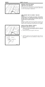
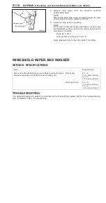
WIPER MOTOR REMOVAL
1.
Remove the wiper motor mounting bolts.
2.
Use a flat-tipped screwdriver to separate the wiper motor
crank arm from the linkage assembly, and then remove
the wiper motor.
Caution
Because the installation angle of the crank arm and
the wiper motor has been set, do not remove them
unless it is necessary to do so. If they must be
removed, remove them only after marking their
mounting positions.
INSTALLATION SERVICE POINTS
"
A
A
WIPER ARM AND BLADE ASSEMBLY
INSTALLATION
Install the wiper blade so that the wipers stops at the specified
stop position (standard value) as shown in the illustration.
Standard value (A): 20
±
5 mm <L.H. drive vehicles>
30
±
5 mm <R.H. drive vehicles>
INSPECTION
WIPER MOTOR CHECK
Disconnect the wiring harness connector, and then check the
wiper motor operation with the wiper motor remaining installed
to the body.
Wiper Motor Operation Speed
Connect a battery to the wiper motor as shown in the illustration
and check the operation speed.
Stop Position
1.
Connect a battery to the wiper motor as shown in the
(A) of the illustration. While the wiper motor operates at
low speed, disconnect the battery to stop the wiper motor.
2.
Connect the terminals via a jumper wire and a battery
to the wiper motor as shown in the (B) of the illustration.
After the motor starts turning at low speed, it should stop
at the automatic stop position.
Linkage
assembly
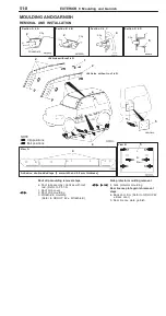
Windshield lower moulding end
A
A
Operation speed check
Low speed High speed
Stop position check
(A) Low
speed
(B) Automatic stop
Summary of Contents for Pajero Pinin 1999
Page 32: ...NOTES ...
Page 73: ...13A 1 FUEL CONTENTS GASOLINE DIRECT INJECTION GDI 13A FUEL SUPPLY 13B ...
Page 190: ...NOTES ...
Page 191: ...13B 1 FUEL SUPPLY CONTENTS FUEL TANK 2 Fuel Pump Module 4 ...
Page 214: ...NOTES ...
Page 222: ...NOTES ...
Page 256: ...NOTES ...
Page 274: ...NOTES ...
Page 282: ...NOTES ...
Page 360: ...NOTES ...
Page 412: ...NOTES ...
Page 443: ...32 1 POWER PLANT MOUNT CONTENTS ENGINE MOUNTING 2 TRANSMISSION MOUNTING 3 ...
Page 446: ...NOTES ...
Page 447: ......
Page 448: ......
Page 449: ......
Page 450: ......
Page 451: ......
Page 452: ......
Page 453: ......
Page 454: ......
Page 455: ......
Page 456: ......
Page 457: ......
Page 458: ......
Page 459: ......
Page 460: ......
Page 461: ......
Page 467: ...NOTES ...
Page 468: ...BASIC BRAKE SYSTEM 35A ANTI SKID BRAKING SYSTEM ABS 4WD 35B 35A 1 SERVICE BRAKES CONTENTS ...
Page 499: ...NOTES ...
Page 531: ...NOTES ...
Page 541: ...NOTES ...
Page 649: ...NOTES ...
Page 728: ...54A 1 CHASSIS ELECTRICAL CONTENTS CHASSIS ELECTRICAL 54A SMART WIRING SYSTEM SWS 54B ...
Page 883: ...NOTES ...
Page 919: ...NOTES ...

