ABS <4WD> ±
On-vehicle Service
35B-22
ON-VEHICLE SERVICE
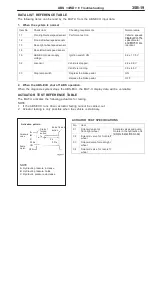
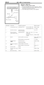
WHEEL SPEED SENSOR OUTPUT VOLTAGE
CHECK
1.
Lift up the vehicle and release the parking brake.
2.
Disconnect the ABS-ECU connector and then connect
the special tool to the harness side connector. (Refer to
P. 35B-27.)
3.
Rotate the wheel to be measured at approximately 1/2± 1
rotation per second, and check the output voltage using a
circuit tester or an oscilloscope.
Wheel speed
sensor
Front
left
Front
right
Rear left
Rear
right
Terminal No.
15
17
2
4
14
18
1
5
Output voltage
When measuring with a circuit tester:
42 mV or more
When measuring with an oscilloscope:
120 mV p-p or more
4.
The followings are suspected if the output voltage is lower
than the value described above. Check the wheel speed
sensor, and replace if necessary.
D
Too large clearance between the pole piece of the
wheel speed sensor and ABS rotor
D
Faulty wheel speed sensor
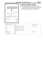
Inspecting Waveforms With An Oscilloscope
Use the following method to observe the output voltage
waveform from each wheel speed sensor with an oscilloscope.
D
Start the engine, and rotate the rear wheels by engaging
1st gear (vehicles with manual transmission) or D range
(vehicles with automatic transmission). Turn the front
wheels manually so that they rotate at a constant speed.
NOTE
1.
The waveform measurements can also be taken while
the vehicle is actually moving.
2.
The output voltage will be small when the wheel speed
is low, and similarly it will be large when the wheel speed
is high.
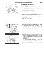
Check connector
MB991547
ABS-ECU
Body side harness
When turning by hand
When idling (5 ± 6 km/h), 1st gear (M/T)
or D range (A/T)
10.0 ms/DIV 1
V/DIV
Summary of Contents for Pajero Pinin 1999
Page 32: ...NOTES ...
Page 73: ...13A 1 FUEL CONTENTS GASOLINE DIRECT INJECTION GDI 13A FUEL SUPPLY 13B ...
Page 190: ...NOTES ...
Page 191: ...13B 1 FUEL SUPPLY CONTENTS FUEL TANK 2 Fuel Pump Module 4 ...
Page 214: ...NOTES ...
Page 222: ...NOTES ...
Page 256: ...NOTES ...
Page 274: ...NOTES ...
Page 282: ...NOTES ...
Page 360: ...NOTES ...
Page 412: ...NOTES ...
Page 443: ...32 1 POWER PLANT MOUNT CONTENTS ENGINE MOUNTING 2 TRANSMISSION MOUNTING 3 ...
Page 446: ...NOTES ...
Page 447: ......
Page 448: ......
Page 449: ......
Page 450: ......
Page 451: ......
Page 452: ......
Page 453: ......
Page 454: ......
Page 455: ......
Page 456: ......
Page 457: ......
Page 458: ......
Page 459: ......
Page 460: ......
Page 461: ......
Page 467: ...NOTES ...
Page 468: ...BASIC BRAKE SYSTEM 35A ANTI SKID BRAKING SYSTEM ABS 4WD 35B 35A 1 SERVICE BRAKES CONTENTS ...
Page 499: ...NOTES ...
Page 531: ...NOTES ...
Page 541: ...NOTES ...
Page 649: ...NOTES ...
Page 728: ...54A 1 CHASSIS ELECTRICAL CONTENTS CHASSIS ELECTRICAL 54A SMART WIRING SYSTEM SWS 54B ...
Page 883: ...NOTES ...
Page 919: ...NOTES ...


