BASIC BRAKE SYSTEM ±
On-vehicle Service
BASIC BRAKE SYSTEM ±
On-vehicle Service
35A-6
ON-VEHICLE SERVICE
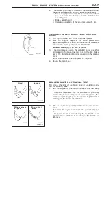
BRAKE PEDAL CHECK AND ADJUSTMENT
BRAKE PEDAL HEIGHT
1.
Turn up the carpet, etc. under the brake pedal.
2.
Measure the brake pedal height as illustrated.
Standard value (A):
<L.H. drive vehicles> 201 ± 204 mm
<R.H. drive vehicles> 201.7 ± 204.7 mm
3.
If the brake pedal height is not within the standard value,
follow the procedure below.
(1) Disconnect the stop lamp switch connector.
(2) Loosen the stop lamp switch by turning it approx.
1/4 turns anticlockwise.
(3) Remove the pin, and then adjust so that the brake
pedal height meets the standard value by turning the
clevis.
NOTE
When the clevis is turned 180
°
, the pedal height is
changed approximately 2.3 mm.
(4) Screw in the stop lamp switch until it touches the
stopper. At this time, support the brake pedal to the
highest position by hand.
(5) Lock the stop lamp switch by turning it approx. 1/4
turns clockwise, and confirm that the clearance
between the switch plunger and the stopper is as
shown.
(6) Connect the connector at the stop lamp switch.
Caution
Check that the stop lamp does not illuminate when
the brake pedal is not depressed.
4.
For A/T, check the key interlock and shift lock mechanisms.
(Refer to GROUP 23 ± On-vehicle Service.)
5.
Return the carpet, etc.
BRAKE PEDAL FREE PLAY
1.
With the engine stopped, depress the brake pedal two
or three times. After eliminating the vacuum in the power
brake booster, press the pedal down by hand, and confirm
that the amount of movement before resistance is met
(the free play) is within the standard value range.
Standard value (B): 3 ± 8 mm
Operating
rod lock nut
Operating rod
Stop lamp switch
A
Stopper
0.5 ± 1.0 mm
B
Summary of Contents for Pajero Pinin 1999
Page 32: ...NOTES ...
Page 73: ...13A 1 FUEL CONTENTS GASOLINE DIRECT INJECTION GDI 13A FUEL SUPPLY 13B ...
Page 190: ...NOTES ...
Page 191: ...13B 1 FUEL SUPPLY CONTENTS FUEL TANK 2 Fuel Pump Module 4 ...
Page 214: ...NOTES ...
Page 222: ...NOTES ...
Page 256: ...NOTES ...
Page 274: ...NOTES ...
Page 282: ...NOTES ...
Page 360: ...NOTES ...
Page 412: ...NOTES ...
Page 443: ...32 1 POWER PLANT MOUNT CONTENTS ENGINE MOUNTING 2 TRANSMISSION MOUNTING 3 ...
Page 446: ...NOTES ...
Page 447: ......
Page 448: ......
Page 449: ......
Page 450: ......
Page 451: ......
Page 452: ......
Page 453: ......
Page 454: ......
Page 455: ......
Page 456: ......
Page 457: ......
Page 458: ......
Page 459: ......
Page 460: ......
Page 461: ......
Page 467: ...NOTES ...
Page 468: ...BASIC BRAKE SYSTEM 35A ANTI SKID BRAKING SYSTEM ABS 4WD 35B 35A 1 SERVICE BRAKES CONTENTS ...
Page 499: ...NOTES ...
Page 531: ...NOTES ...
Page 541: ...NOTES ...
Page 649: ...NOTES ...
Page 728: ...54A 1 CHASSIS ELECTRICAL CONTENTS CHASSIS ELECTRICAL 54A SMART WIRING SYSTEM SWS 54B ...
Page 883: ...NOTES ...
Page 919: ...NOTES ...


