GDI ±
On-vehicle Service
13A-99
FUEL LEAK CHECK
1.
Connect the MUT-
II
to the diagnosis connector.
2.
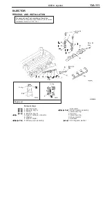
Disconnect the injector intermediate harness connector.
3.
Turn the ignition switch to ON.
4.
Select ªItem No.74º from the MUT-
II
Data list.
5.
Crank the engine continuously for two seconds or more,
and visually check that there are no fuel leaks from any
parts.
Caution
If any fuel leaks appear, stop cranking immediately
and repair the source of the leak.
6.
Crank the engine, and then measure fuel pressure
immediately after 20 seconds.
Limit: Minimum 1 MPa
Caution
If the fuel pressure is less than 1 MPa, there may
be a partial fuel leak in the high-pressure fuel system.
7.
Turn off the ignition switch.
8.
Reconnect the injector intermediate connector.
9.
Remove the MUT-
II
.
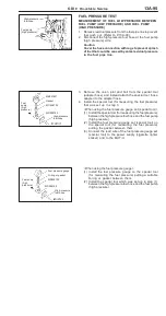
FUEL PUMP CONNECTOR DISCONNECTION
(HOW TO REDUCE FUEL PRESSURE)
When removing the fuel pipe, hose, etc., since fuel pressure
in the fuel pipe line is high, do the following operation so
as to release fuel pressure in the line and prevent fuel from
running out.
1.
Remove the fuel filler cap to release pressure in the fuel
tank.
2.
Remove the fuel pump relay.
3.
Connect the MUT-
II
to the diagnosis connector.
Caution
Turn off the ignition switch before disconnecting or
connecting the MUT-
II
.
4.
Turn off the ignition switch.
5.
Select ªItem No.74º from the MUT-
II
Data list.
6.
Crank the engine for at least two seconds.
7.
If the engine is not be started, use the MUT-
II
to make
sure that the fuel pressure is 0.5 MPa or less. Then turn
off the ignition switch.
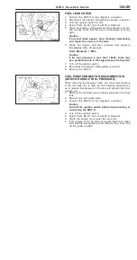
Injector
intermediate
harness
connector
Fuel pump relay
Summary of Contents for Pajero Pinin 1999
Page 32: ...NOTES ...
Page 73: ...13A 1 FUEL CONTENTS GASOLINE DIRECT INJECTION GDI 13A FUEL SUPPLY 13B ...
Page 190: ...NOTES ...
Page 191: ...13B 1 FUEL SUPPLY CONTENTS FUEL TANK 2 Fuel Pump Module 4 ...
Page 214: ...NOTES ...
Page 222: ...NOTES ...
Page 256: ...NOTES ...
Page 274: ...NOTES ...
Page 282: ...NOTES ...
Page 360: ...NOTES ...
Page 412: ...NOTES ...
Page 443: ...32 1 POWER PLANT MOUNT CONTENTS ENGINE MOUNTING 2 TRANSMISSION MOUNTING 3 ...
Page 446: ...NOTES ...
Page 447: ......
Page 448: ......
Page 449: ......
Page 450: ......
Page 451: ......
Page 452: ......
Page 453: ......
Page 454: ......
Page 455: ......
Page 456: ......
Page 457: ......
Page 458: ......
Page 459: ......
Page 460: ......
Page 461: ......
Page 467: ...NOTES ...
Page 468: ...BASIC BRAKE SYSTEM 35A ANTI SKID BRAKING SYSTEM ABS 4WD 35B 35A 1 SERVICE BRAKES CONTENTS ...
Page 499: ...NOTES ...
Page 531: ...NOTES ...
Page 541: ...NOTES ...
Page 649: ...NOTES ...
Page 728: ...54A 1 CHASSIS ELECTRICAL CONTENTS CHASSIS ELECTRICAL 54A SMART WIRING SYSTEM SWS 54B ...
Page 883: ...NOTES ...
Page 919: ...NOTES ...


