FRONT AXLE ±
Drive Shaft
26-20
A
B
"
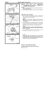
TIE
ROD
END
AND
HUB/KNUCKLE
ASSEMBLY/LOWER ARM AND HUB/KNUCKLE
ASSEMBLY DISCONNECTION
Caution
1.
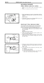
Only loosen the ball joint nut, but do not remove it.
Use the special tool.
2.
Tie the special tool with a cord not to let it fall off.
A
C
"
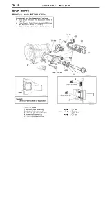
DRIVE SHAFT REMOVAL
1.
For the left side drive shaft, pry the D.O.J. stepped part
with a tyre lever, and then withdraw the drive shaft from
the free-wheeling hub assembly.
Caution
Always use a tyre lever. When the drive shaft is
withdrawn from the B.J. assembly, the D.O.J. may
be damaged.
2.
For the right side drive shaft, install the drive shaft with
the castle nut loosely. Then pull the strut, the hub/knuckle
assembly and the lower arm towards you, and then
withdraw the drive shaft from the front differential.
Caution
Be sure to maintain the drive shaft horizontally not
to bend the D.O.J. at extreme angle when the drive
shaft is withdrawn.
3.
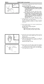
If it is difficult to withdraw the drive shaft from the
hub/knuckle assembly, use the special tools.
Caution
Do not apply the vehicle weight to the wheel bearing
as possible while the drive shaft is removed. If it is
impossible, use the special tool to hold the the wheel
bearing as shown in the illustration.
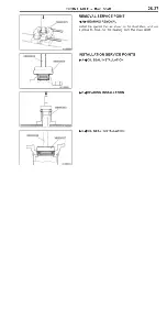
INSTALLATION SERVICE POINT
"
A
A
WASHER/CASTLE NUT INSTALLATION
Refer to P. 26-15.
Nut
Ball joint
Cord
MB991113 or
MB991406
Tyre lever
D.O.J.
Stepped part
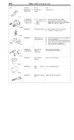
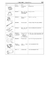
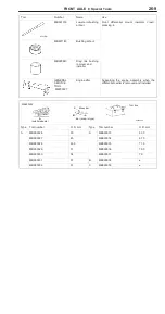
MB990244
(Three)
MB991354
MB990242
MB990767
MB991017
MB991000
(MB990998)
Summary of Contents for Pajero Pinin 1999
Page 32: ...NOTES ...
Page 73: ...13A 1 FUEL CONTENTS GASOLINE DIRECT INJECTION GDI 13A FUEL SUPPLY 13B ...
Page 190: ...NOTES ...
Page 191: ...13B 1 FUEL SUPPLY CONTENTS FUEL TANK 2 Fuel Pump Module 4 ...
Page 214: ...NOTES ...
Page 222: ...NOTES ...
Page 256: ...NOTES ...
Page 274: ...NOTES ...
Page 282: ...NOTES ...
Page 360: ...NOTES ...
Page 412: ...NOTES ...
Page 443: ...32 1 POWER PLANT MOUNT CONTENTS ENGINE MOUNTING 2 TRANSMISSION MOUNTING 3 ...
Page 446: ...NOTES ...
Page 447: ......
Page 448: ......
Page 449: ......
Page 450: ......
Page 451: ......
Page 452: ......
Page 453: ......
Page 454: ......
Page 455: ......
Page 456: ......
Page 457: ......
Page 458: ......
Page 459: ......
Page 460: ......
Page 461: ......
Page 467: ...NOTES ...
Page 468: ...BASIC BRAKE SYSTEM 35A ANTI SKID BRAKING SYSTEM ABS 4WD 35B 35A 1 SERVICE BRAKES CONTENTS ...
Page 499: ...NOTES ...
Page 531: ...NOTES ...
Page 541: ...NOTES ...
Page 649: ...NOTES ...
Page 728: ...54A 1 CHASSIS ELECTRICAL CONTENTS CHASSIS ELECTRICAL 54A SMART WIRING SYSTEM SWS 54B ...
Page 883: ...NOTES ...
Page 919: ...NOTES ...

