


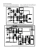


5-7
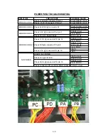
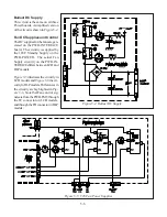
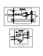
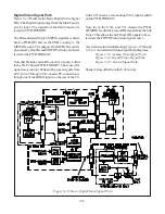
PWB-ENG-PWR
It was previously mentioned that the PWB-ENG-PWR
board is added in DLP models.
Figure 5-7
shows this
circuitry. It is basically a PWM Regulator with a push
pull FET output circuit, generating a 2.5V supply for the
DLP Engine. The board also serves as an interface for
the 12V, 5V and 3.3V Standby supplies from PWB-
POWER.
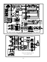
Hard Disc 7Drive (HDD) Supply
Additional power supply circuitry is required for the
V30+ and V31 chassis. Both of these chassis types
feature a Hard Disc Drive. Added power circuitry for
the HDD is on the PWB-POWER, refer to
Figure 5-8.
Note that the Fan Stop monitoring circuit for the HDD
is also added to PWB POWER.
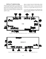
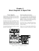
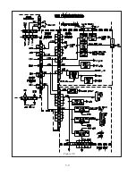
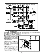
Power Distribution
When a specific PWB is suspected as the cause of a
problem, the following should be checked before or-
dering a new board:
• Power supply voltages supplied to the PWB.
• Signals supplied to the PWB.
Power Distribution diagrams are helpful in locating the
source of a missing power supply voltage.
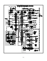
Figure 5-9
shows the Power Distribution for the V28 chassis. Fig-
ure 5-10 illustrates Power Distribution in the DLP chas-
sis. Although the two chassis types are similar there are
some differences. The shaded areas in
Figure 5-1
0
indicate differences from the V28 chassis.
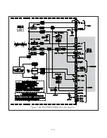
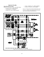
Figure 5-6: V29/V30/V30+/V31 Fan Supplies
Summary of Contents for Mr.Slim WD-52627
Page 2: ......
Page 4: ...II...
Page 50: ...4 8...
Page 54: ...5 4 Figure 5 3A V28 PWB POWER DC to DC Supplies...
Page 55: ...5 5 Figure 5 3B DLP PWB POWER DC to DC Supplies...
Page 58: ...5 8 Figure 5 7 DLP Engine Power Supply Figure 5 8 Hard Disc HDD Power Supply V30 and V31 Only...
Page 59: ...5 9 Figure 5 9...
Page 60: ...5 10 Figure 5 10...
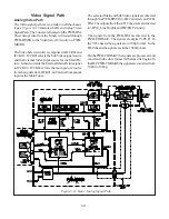
Page 63: ...5 13 Figure 5 13 Analog Video Signal Path...
Page 64: ...5 14 Figure 5 15 Video Record Path V30 and V31 only Figure 5 14 Analog Video Signal Path...
Page 69: ...5 19 Figure 5 22 DLP Engine Protect Circuitry Figure 5 23 Short Detection Circuitry...
Page 70: ...5 20...
Page 71: ......