


1-2
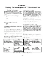
Light Engines
The CRT technology used in the V27 chassis is electri-
cally the same as the V25 chassis. Since the V25 Train-
ing Manual covers it in-depth, no further discussion will
be necessary.
LCD, DLP and LCoS are known as “Micro-Display”
technologies. The Light Engines are configured differ-
ently for each.
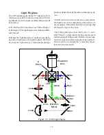
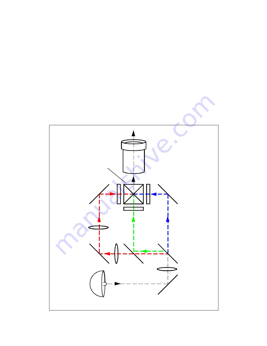
LCD uses the “light transmissive” method of producing
a picture as light passes through the panel. DLP and
LCoS use the “light reflective” method of producing a
Figure 1-1: LCD Light Engine
picture as light reflects off the surface of the display de-
vice.
An LCD must use 3 devices to produce a color picture.
DLP and LCoS can be configured as either single, or 3
device engines. Mitsubishi currently uses a single chip
DLP and a 3 chip LCoS system.
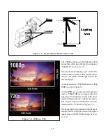
The LCD Light Engine, shown in
Figure 1-1,
uses 3
LCD “Panels” to individually produce the red, green
and blue elements of the picture. Dichroic mirrors sepa-
rate the red, green and blue elements of light, and an X-
Prism is used to re-combine the 3 colors after the pic-
tures have been produced.
Projection
Lens
Mirror
Red
Blue
X
Prism
Dichroic
Mirror
Green
Dichroic
Mirror
Lens
Lens
Lens
Mirror
Mirror
Lamp
LCD
LCD
LCD
Summary of Contents for Mr.Slim WD-52627
Page 2: ......
Page 4: ...II...
Page 50: ...4 8...
Page 54: ...5 4 Figure 5 3A V28 PWB POWER DC to DC Supplies...
Page 55: ...5 5 Figure 5 3B DLP PWB POWER DC to DC Supplies...
Page 58: ...5 8 Figure 5 7 DLP Engine Power Supply Figure 5 8 Hard Disc HDD Power Supply V30 and V31 Only...
Page 59: ...5 9 Figure 5 9...
Page 60: ...5 10 Figure 5 10...
Page 63: ...5 13 Figure 5 13 Analog Video Signal Path...
Page 64: ...5 14 Figure 5 15 Video Record Path V30 and V31 only Figure 5 14 Analog Video Signal Path...
Page 69: ...5 19 Figure 5 22 DLP Engine Protect Circuitry Figure 5 23 Short Detection Circuitry...
Page 70: ...5 20...
Page 71: ......