


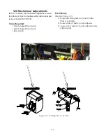
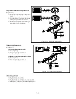
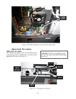


3-1
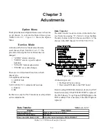
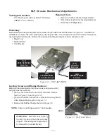
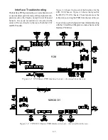
Option Menu
The Option Menu and Option Menu access is the same
on all chassis. To activate the Option Menu press
“MENU-2-4-7-0”.
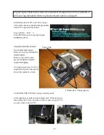
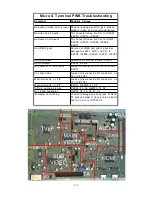
Figure 3-1
shows the Option
Menu.
Service Mode
Activation of the Service Mode is also the same
on all chassis, Press “MENU-2-4-5-7”. The
procedure for using the Service Mode has not
changed:
• “AUDIO” selects a function
• “VIDEO” selects a specific adjust-
ment item
• “UP & DN’ buttons adjusts data
• “ENTER” saves data changes.
There are two Adjustment Function on Each
chassis type.
V28 Adjustment Functions
1) AD9881 Sub
2) fmt
V29/V30/V30+/V31 Adjustment Functions
1) Doubler
2) fmt
In either case, only the “fmt” function is used to perform
service Adjustments.
Chapter 3
Adustments
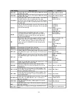
Data Transfer
"MENU-2-4-5-7-0"
Display
Description
Restore Back Up
Resets data to factory values
Upload Terminal Data
Not used
Down load WB data to FMT
Use after replacing Engine PWB-FORMAT
Table 3-1: V28 Data Transfer Choices
Data Transfer
The data Transfer mode is activated when in the Ser-
vice Mode by pressing “0”.
Table 3-1
show the Data
Transfer choices in the V28 chassis, and
Table 3-2
the
choices in the DLP chassis (V29/V30/V30+/V31)
All chassis types can:
• Be Reset to Factory values
• Down load WB data to the FMT board
Down loading WB (White Balance) data to the FMT
board is necessary if the PWB-FORMAT is replaced.
The DLP chassis, “Copy Engine E2PROM data to the
DM” is added. This is necessary if the DLP Engine is
replaced.
Figure 3-1: Option Menu
Summary of Contents for Mr.Slim WD-52627
Page 2: ......
Page 4: ...II...
Page 50: ...4 8...
Page 54: ...5 4 Figure 5 3A V28 PWB POWER DC to DC Supplies...
Page 55: ...5 5 Figure 5 3B DLP PWB POWER DC to DC Supplies...
Page 58: ...5 8 Figure 5 7 DLP Engine Power Supply Figure 5 8 Hard Disc HDD Power Supply V30 and V31 Only...
Page 59: ...5 9 Figure 5 9...
Page 60: ...5 10 Figure 5 10...
Page 63: ...5 13 Figure 5 13 Analog Video Signal Path...
Page 64: ...5 14 Figure 5 15 Video Record Path V30 and V31 only Figure 5 14 Analog Video Signal Path...
Page 69: ...5 19 Figure 5 22 DLP Engine Protect Circuitry Figure 5 23 Short Detection Circuitry...
Page 70: ...5 20...
Page 71: ......


