


5-17
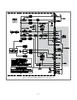
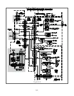
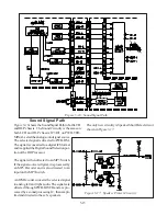
Figure 5-19: V28 Lamp Control Circuitry
Lamp Control Circuitry
Figure 5-19
shows the Lamp Control Circuitry in V28
chassis, and
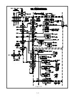
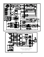
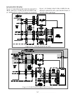
Figure 5-20
the circuitry in the DLP chas-
sis. Differences from the V28 chassis are shaded in
Figure 5-20.
Mainly in the V28 the LAMP-EN com-
mand is from the FMT µPC, and in the DLP chassis it
comes from the Light Engine
Figure 5-20: DLP Chassis Lamp Control Circuitry
Summary of Contents for Mr.Slim WD-52627
Page 2: ......
Page 4: ...II...
Page 50: ...4 8...
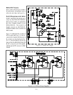
Page 54: ...5 4 Figure 5 3A V28 PWB POWER DC to DC Supplies...
Page 55: ...5 5 Figure 5 3B DLP PWB POWER DC to DC Supplies...
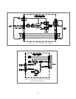
Page 58: ...5 8 Figure 5 7 DLP Engine Power Supply Figure 5 8 Hard Disc HDD Power Supply V30 and V31 Only...
Page 59: ...5 9 Figure 5 9...
Page 60: ...5 10 Figure 5 10...
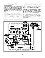
Page 63: ...5 13 Figure 5 13 Analog Video Signal Path...
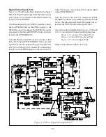
Page 64: ...5 14 Figure 5 15 Video Record Path V30 and V31 only Figure 5 14 Analog Video Signal Path...
Page 69: ...5 19 Figure 5 22 DLP Engine Protect Circuitry Figure 5 23 Short Detection Circuitry...
Page 70: ...5 20...
Page 71: ......


