


5-1
Chapter 5
Block Diagrams & Signal Path
Power Supplies
Although the LCD Light Engine models (V28 chassis)
and DLP Light Engine models (V29, V30, V30+,V31)
are different, a large part of the circuitry is the same or
very similar in all chassis types.
The material in this chapter covers differences in cir-
cuitry between the LCD and DLP chassis. Since
troubleshooting will be mainly to board level, the Power
Supplies, Signal Path and Control circuitry connections
and paths between the various PWBs is also described.
The simplified Block Diagrams should help in isolating
problems to a specific PWB.
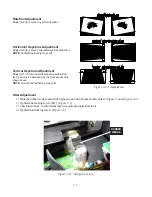
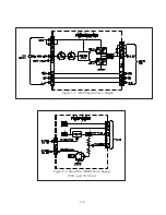
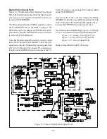
Power Supply Basic Description
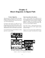
Figure 5-1
shows the Basic Power Supply that is the
basis for all the chassis types. The Main Power Supply
is on PWB-POWER. The main Standby, Switched and
Ballast DC supplies are generated on the PWB-
POWER. It is also the source for the Fan Power Sup-
plies located on the PWB-INTERFACE.
On the DLP chassis, a PWB-ENG-PWR board is
added. This board generates the DC supplies required
by the DLP Engine.
In the V30+ and V31 chassis models, a Hard Disc Drive
(HDD) has been added. The additional Power Supply
Figure 5-1: Basic Power Supply Block Diagram
Summary of Contents for Mr.Slim WD-52627
Page 2: ......
Page 4: ...II...
Page 50: ...4 8...
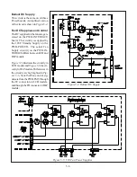
Page 54: ...5 4 Figure 5 3A V28 PWB POWER DC to DC Supplies...
Page 55: ...5 5 Figure 5 3B DLP PWB POWER DC to DC Supplies...
Page 58: ...5 8 Figure 5 7 DLP Engine Power Supply Figure 5 8 Hard Disc HDD Power Supply V30 and V31 Only...
Page 59: ...5 9 Figure 5 9...
Page 60: ...5 10 Figure 5 10...
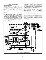
Page 63: ...5 13 Figure 5 13 Analog Video Signal Path...
Page 64: ...5 14 Figure 5 15 Video Record Path V30 and V31 only Figure 5 14 Analog Video Signal Path...
Page 69: ...5 19 Figure 5 22 DLP Engine Protect Circuitry Figure 5 23 Short Detection Circuitry...
Page 70: ...5 20...
Page 71: ......


