


5-2
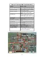
for the HDD is located on the PWB-POWER for these
two chassis types.
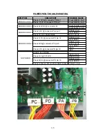
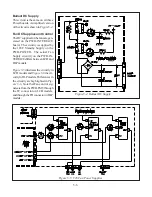
Due to differences between the various chassis there
are three version of the PWB-POWER. These are listed
in
Table 5-1.
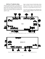
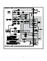
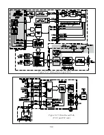
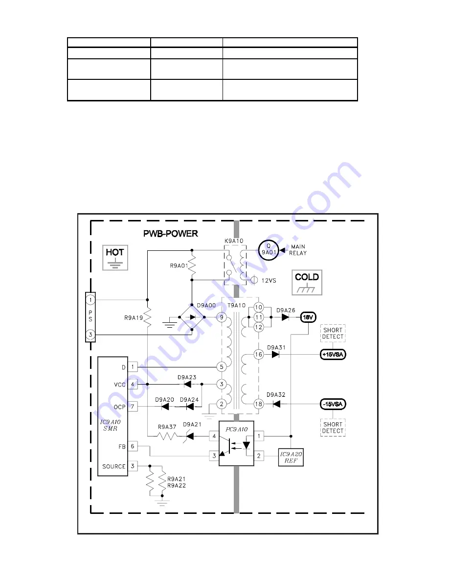
Switch Mode Regulator
The Switch Mode Regulator (SMR) on the PWB-
POWER is the initial source for all DC Supplies except
the DC supply for the Ballast.
Figure 5-2
shows a simplified diagram of the Switch
Mode Regulator. This circuitry is conventional and is
Figure 5-2: Switch Mod Regulator
PWB
Part Number
Models
ASSY-PWB-POWER1
930B933001
All V28 models
ASSY-PWB-POWER2
934C159001
WD-52627 / WD-52628 / WD-62627 /
WD-62628 / WD-73727
ASSY-PWB-POWER2
934C159002
WD-62727 / WD-62927 / WD-73827 /
WD-73927
Table 5-1: PWB-POWER Part Numbers
Summary of Contents for Mr.Slim WD-52627
Page 2: ......
Page 4: ...II...
Page 50: ...4 8...
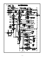
Page 54: ...5 4 Figure 5 3A V28 PWB POWER DC to DC Supplies...
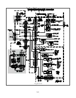
Page 55: ...5 5 Figure 5 3B DLP PWB POWER DC to DC Supplies...
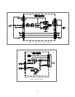
Page 58: ...5 8 Figure 5 7 DLP Engine Power Supply Figure 5 8 Hard Disc HDD Power Supply V30 and V31 Only...
Page 59: ...5 9 Figure 5 9...
Page 60: ...5 10 Figure 5 10...
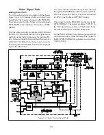
Page 63: ...5 13 Figure 5 13 Analog Video Signal Path...
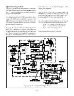
Page 64: ...5 14 Figure 5 15 Video Record Path V30 and V31 only Figure 5 14 Analog Video Signal Path...
Page 69: ...5 19 Figure 5 22 DLP Engine Protect Circuitry Figure 5 23 Short Detection Circuitry...
Page 70: ...5 20...
Page 71: ......


