


4-1
Chapter 4
Down-to-1
Troubleshooting
The goal of
Down-to-1
troubleshooting is…
using a
minimum amount of time and test equipment, make
an accurate diagnosis of a failure 9 out of 10 times.
The 2005-2006 Micro-Display product line lends itself
to this discipline very well.
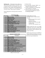
Using The Front Panel LEDs
The front panel LEDs,
Figure 4-1
, provide an indica-
tion of the sets operation, and the possible cause of a
malfunction. There are three front panel LEDs, “Power”,
“Status” and “Lamp”. Which LED is lit, the color and
whether it is blinking or steady indicates to the customer
the current status, or a possible malfunction. Using the
Front Panel LEDs is similar for LCD and DLP based
sets. The indications are also listed in the Owners Guide.
Figure 4-1: Front Panel LEDs
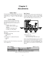
Normal Indications
… The LEDs provide the cus-
tomer with status information that indicates several nor-
mal operational modes. Normal indications are give in
Table 4-1
.
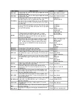
Abnormal Indications
… The LEDs also provide the
customer with status information indicating abnormal con-
ditions. Abnormal indications are give in
Table 4-2
.
POWER
LED
STATUS
LED
LAMP
LED
Power
Status
Condition
Off
Off
Off
Stby
Off
Green
Off
Off
P-0N
Power On
Off
Off
Blinks
Green
30
Seconds
After Off
Set cannot be turned On until
Lamp has cooled.
Blinks
Green
Off
Off
Stby
Booting after AC applied
Slow Blinks
Green
Off
Off
Stby
On Timer is set
POWER
LED
STATUS
LED
LAMP
LED
Power
Status
Condition
Off
Yellow
Off
Low
Power
Excess Temperature
Off or On
Off
Yellow
No
change
Lamp time over 4000 Hrs.
Off
Off
Blinks
Yellow
Low
Power
Lamp Cover open
Off
Blinks
Yellow
Off
"
Filter Cover Open (V28 Only)
Off
Off
Red
Stby
Lamp did not turn On
Off
Blinks
Red
Off
Low
Power
Fan Stopped
Off
Red
Off
"
Circuit Failure
Normal LED Indications
Abnormal LED Indications
Table 4-1
Table 4-2
Summary of Contents for Mr.Slim WD-52627
Page 2: ......
Page 4: ...II...
Page 50: ...4 8...
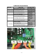
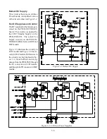
Page 54: ...5 4 Figure 5 3A V28 PWB POWER DC to DC Supplies...
Page 55: ...5 5 Figure 5 3B DLP PWB POWER DC to DC Supplies...
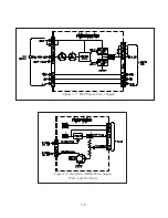
Page 58: ...5 8 Figure 5 7 DLP Engine Power Supply Figure 5 8 Hard Disc HDD Power Supply V30 and V31 Only...
Page 59: ...5 9 Figure 5 9...
Page 60: ...5 10 Figure 5 10...
Page 63: ...5 13 Figure 5 13 Analog Video Signal Path...
Page 64: ...5 14 Figure 5 15 Video Record Path V30 and V31 only Figure 5 14 Analog Video Signal Path...
Page 69: ...5 19 Figure 5 22 DLP Engine Protect Circuitry Figure 5 23 Short Detection Circuitry...
Page 70: ...5 20...
Page 71: ......


