background image


13

1.4.3 Starting the On-Line Monitor(G-50 connection)   

 
* To use the maintenance tool via G-50 (Network), license registration for the G-50 to be used is necessary. 
Purchasing the license No. for each G-50 to be used, conduct the license registration through the Web 
browser (http://[IP address of the G-50A]/ administrator.html). After selecting "Maintenance tool" of the 
optional function on the Web Browser Screen displayed, enter the purchased license No.. 
For the detail of the license registration, see Chapter 4 [Registering a License for Optional Functions] of 
Central Controller Model: G-50A Web Browser Operation Manual (For manager).   


* To use the maintenance tool via G-50 (Only for LAN mode and Dialup connection mode), please check a 
setup of Internet Connection Firewall of PC. If the FIREWALL function is used, communication will be 
normally impossible with G-50A, and normal data will not be displayed.   
For detail, please refer to 

[6. How to change setting of Firewall] on Page 57.


In the case of permanently installing an anti-virus software and always started under this environment, the 
fire wall function of this software may be activated sometimes. In such case, The normal communication with 
G-50 will be hindered not displaying data normally. When operating Maintenance Tool, finish the anti-virus 
software once or remove the fire wall function. 


1.4.3.1 In case for local connection   

In the case when on line monitoring is applied to air conditioning system via G-50 by connecting the 
maintenance tool to LAN locally.   
 
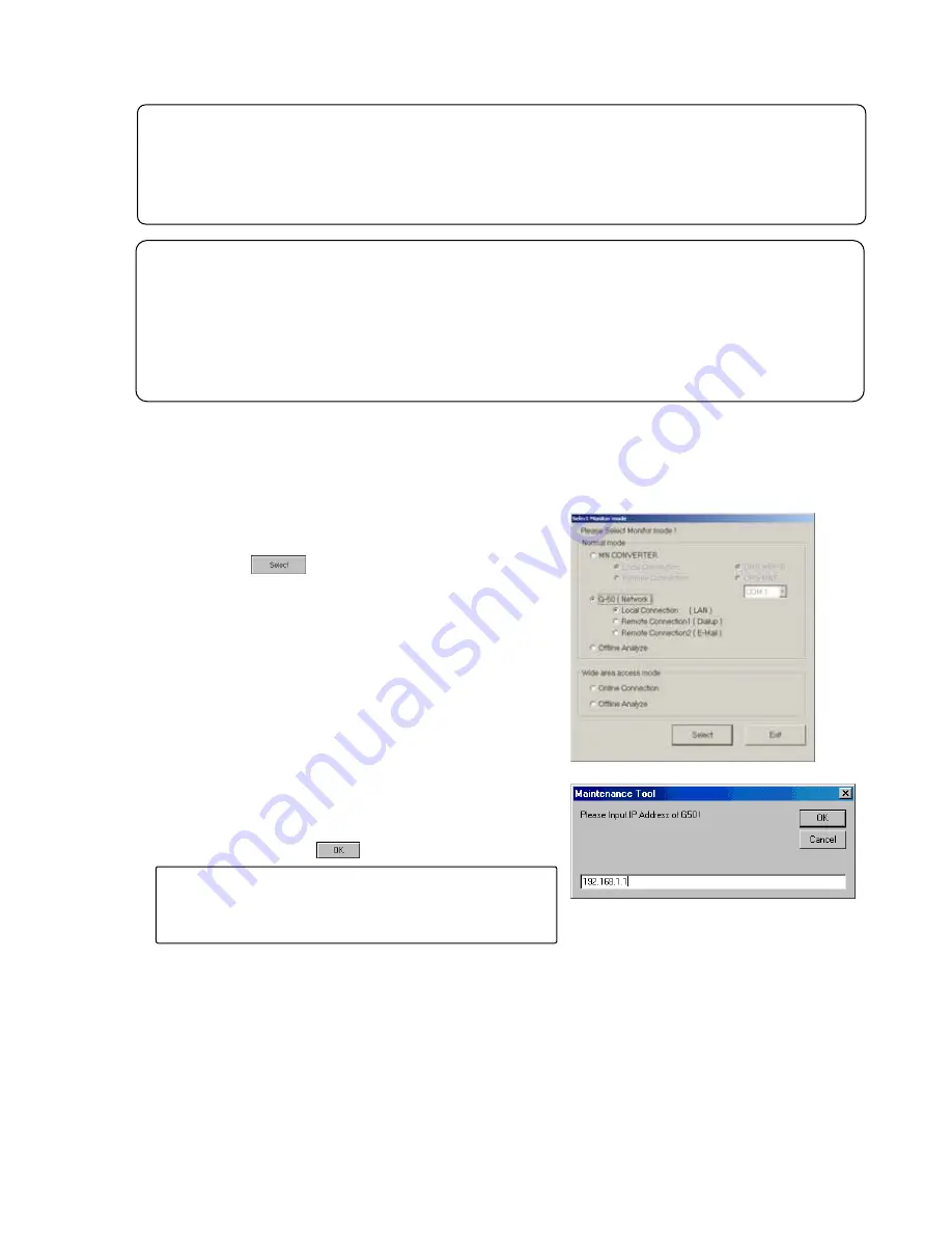
(1) Clicking "G-50(Network)" on the selection screen of 

Monitor mode selects "Local connection" simultaneously. 
Last click "                ." 


(2)  Next IP address input screen is displayed. Here,input IP 

address of G-50A connected to the air conditioning 
system of which operating information is desired to 
monitor, and click on       . 


Request


It is required to set to the IP address in the same system with
G-50 to be connected to Maintenance Tool PC from   
[Control Panel]. 

Summary of Contents for G-50A

Page 1: ...ction Operations 27 3 6 Connecting Information 27 3 7 Operation Monitor 29 3 8 Malfunction Log 37 3 9 Optional Setting 39 3 10 Operation Control 42 3 11 Free contact of indoor unit 44 4 Off Line Monitor Operating Method 4 1 Off Line Monitor Screen Transfer 46 4 2 Function Chart 47 4 3 Operation Monitor 48 4 4 System Information 52 4 5 Monitoring of Pre error Data 53 4 6 Filing Operation 54 4 7 Off...

Page 2: ...stering a License for Optional Functions of Central Controller Model G 50A Web Browser Operation Manual For manager 1 1 1 On Line Monitor via MN converter The On Line Monitor is connected to the unit by a MN Converter CMS MNF and can monitor such areas as system data unit data and operating data 1 In case for local connection Connecting PC installed with the maintenance tool to M NET transmission ...

Page 3: ...rovider2 Mail server SMTP POP SMTP Mail server Mail server E mail E mail Notice To use the E mail connection mode the version of G 50 should be above 2 60 When using E mail connection mode the local G 50A is required to be initially set with Maintenance Tool and the mail address by the G 50A initial setting tool For each mail address it is required to obtain and set an exclusive one To transmit ma...

Page 4: ...ditioning system of the customer desired to be accessed Remote access method LAN Accessing by directly connecting Maintenance Tool PC and G 50A with LAN WAN Dialup Accessing by dialup connection to G 50A via public network E mail Accessing by E mail communication to G 50A via mail server Modem MN Converter Accessing by connecting Modem to MN Converter via public telephone circuit After the online ...

Page 5: ...onnection are required RS 232 C is to be straight cable in this case For detail please see Installation Manual annexing of MN Converter CMS MNF 2 In case of routing via G 50 G 50 personal computer LAN cable Straight and HUB A dial up router is required for remote communication For the dial up router to be used employ that allowing data communication by receiving external telephone transmission 1 A...

Page 6: ... database Execute Setup bat located in the folder of SetUp 2_DB_SETUP of CD ROM Double clicking on Setup bat with the explorer displays the command prompt screen The setting up processing ends within about 10 seconds 3 minutes After ending of the setting up Press any key to continue is displayed Pressing any key closes the command prompt screen Request For setting up be sure to practice 3 steps in...

Page 7: ...he installation folder C drive only Use Previous button After confirming the installation folder click on Next button Clicking on Cancel button stops installation procedure 3 Confirming the installation start 1 Confirm the starting and select Next button Clicking on Next button starts installation Clicking on Cancel button stops installation 4 Confirming the completion of Maintenance Tools setup 1...

Page 8: ...displayed at the bottom of the screen Please wait for this display About 10 seconds 3 minutes are required to complete the set up processing The screen will be closed by pressing any button after completing the processing with the display of Press any key to continue Step 4 Upgrade the Maintenance Tool Execute setup exe located in VerUp 2_MNTTOOL_UPDATE folder of CD ROM Double clicking on setup ex...

Page 9: ...s 2000 and XP and press Change Remove button Select Maintenance Tool for windows 2000 and XP from the application and click on Remove button The deletion of Maintenance Tools application starts 4 Ending the Add Remove Programs After ending the deletion of application end Add Remove Programs 1 3 4 RE Change of computer name on PC Do not change the computer name after the Maintenance tool has been s...

Page 10: ... tool counts for 2G bite maximum When the remaining storage capacity is insufficient at starting Warning Screen will appear In this case move to OFF Line Screen to delete unnecessary data 5 Thereafter the selection screen of Monitor mode is displayed Selecting the mode to be adapted Normal mode a ON LINE MODE MN CONVERTER When on line monitoring is adapted to air conditioning system by connecting ...

Page 11: ...tion of the on site air conditioner system connection method refer to the MN Converter Operation Manual If communication does not have for 10 minutes in remote connection Timeout occurred will be displayed if O K is pushed a telephone circuit will be cut automatically and the Maintenance tool will be ended 1 After clicking MN CONVERTER on the selection screen of Monitor mode and click REMOTE CONNE...

Page 12: ...another modem Send the initialize command and register the transfer contents for the modem at the AT Command Transmit Screen Refer to b Click on to delete the selected modem settings from the registered settings When the number of registrations limit is exceeded delete the unwanted contents Refer to b Click on to return to the Connection Setting Screen b Perform new modem setup Enter the command y...

Page 13: ... a telephone number is 0123456789 ATDT0123456789 is transmitted to the modem It becomes the following when DP NONE are chosen in the same way DP ATDP0123456789 NONE ATD0123456789 When a circuit connection is impossible in the case of above three which as well ELSE is used When ELSE is chosen nothing is added to before the telephone number Input a command for the circuit connection from the beginni...

Page 14: ...ill not be displayed For detail please refer to 6 How to change setting of Firewall on Page 57 In the case of permanently installing an anti virus software and always started under this environment the fire wall function of this software may be activated sometimes In such case The normal communication with G 50 will be hindered not displaying data normally When operating Maintenance Tool finish th...

Page 15: ...ion on the receiver the dial up router at G 50A in the field of the telephone transmission onto the dial up connection screen If communication does not have for 10 minutes in remote connection Timeout occurred will be displayed if O K is pushed a telephone circuit will be cut automatically and the Maintenance tool will be ended 1 After clicking G 50 Network on the selection screen of Monitor mode ...

Page 16: ...sign earlier G 50A open the address book to select Notice To use the E mail connection mode the version of G 50 should be above 2 60 When using E mail connection mode the local G 50A is required to be initially set with Maintenance Tool and the mail address by the G 50A initial setting tool For each mail address it is required to obtain and set an exclusive one To transmit mail via an internet pro...

Page 17: ...the address book of the project After fitting the cursor to the name of address of G 50A click SELECT button c Advanced setting screen Clicking Open Advanced opens Advanced screen where the mail information about Maintenance Tool may be set When the mail information about Maintenance Tool has not been set Advanced screen is displayed always under opened state Setting of mail information on Mainten...

Page 18: ... Accessing by dialup connection to G 50A via public network E mail Accessing by E mail communication to G 50A via mail server Modem MN Converter Accessing by connecting Modem to MN Converter via public telephone circuit After the online connection performed by any of the above methods you may use the similar function as that obtainable in the normal online connection While under the offline mode c...

Page 19: ...A name appears set a proper Area name and press OK to create the Area folder b Creating the Customer name folder 1 Right clicking the Area name folder to be registered displays the sub menu 2 Select Create Custormer 3 As the screen to enter the Customer name appears set a proper customer name In addition to the above mouse operation the creation of AREA name and Customer name can be set from the m...

Page 20: ...as 1 4 3 1 To connect by using Dial up select the Connection name of dialup router of the local G 50 being previously set on the dialup connection screen of Windows And enter User name and Password for the connection with the dialup router and lastly enter the IP address of G 50 Same as1 4 3 2 To connect under E mail mode enter the E mail address of G 50 to be connected Refer to1 4 3 3 To connect ...

Page 21: ...Transmitting SMTP server address Set the IP address of transmitting mail server of Maintenance Tool 3 Mail address Set the mail address of Maintenance Tool Clicking Close Advanced closes Advanced screen Setting of Com port To connect Mode select the Com port to be used 3 Focussing on the air conditioning system desired to be connected and pressing Connect will start the procedure for connection Af...

Page 22: ...matically be disconnected Clicking returns to the selection screen of Monitor mode 1 4 6 2 Ending the Off Line Monitor 1 Open the Off line Analyze Screen 2 Click on 3 The message Are you sure you want to finish maintenance tool will appear Click on When finishing Offline Screen immediately after deleting data a message of Finishing Maintenance Tool may sometime be displayed The internal data is no...

Page 23: ...wing operations are performed by mouse 1 Click Align the mouse pointer with the desired button and press the left button on the mouse This is known as a click In general all maintenance tool operations are performed with click operations 2 Drag A drag is when the mouse pointer is moved while the left button is held down If you desired to check the bottom screen when two or more screens are being d...

Page 24: ...23 3 1 On Line Monitor Screen Transfer 3 On Line Monitor Operating Method Title Screen Main Screen Malfunction Log Operation Control Connecting Information Operation Monitor Optional Setting ...

Page 25: ... Refer to 3 8 This allows monitoring of the ten most recent errors of the unit Optional Setting Refer to 3 9 This allows monitoring of self diagnosis function operation control and pre error data monitoring This also allows to monitor the response to any M NET command transmitted to the unit Time setting Operation Control Refer to 3 10 This allows the same operation as with the remote controller 3...

Page 26: ...ddresses can be searched for Click on to end automatic search The Main Screen will appear 2 When automatic search has ended the Main Screen will appear Returning to the Main Screen enables the Function Buttons 3 3 3 Manual Searching 1 Click on and the Main Screen will appear 2 Click on the Button of the address desired and searching will begin Note When a system is changed please search an address...

Page 27: ... line monitor Refer to 1 4 5 1 Ending the On Line Monitor Click on Option and Automatic searching and the Stop mail communication sub menus can be selected At the connection of MN Converter Stop mail communication is not displayed Click on Automatic searching and the message Start the automatic searching Is it OK will appear Click on to perform automatic searching or click on to return to the Main...

Page 28: ...oup SC remote controller only the Connecting Information Screen will display as a pop up menu The screen displays addresses and attributes of the units connected to the select unit 3 6 1 Screen Transfer Operation 1 Click on on the Main Screen 2 Click on the for the outdoor unit to be monitored Only outdoor units can be selected 3 Momentarily the message Monitoring Please wait for a moment will app...

Page 29: ...ch connected unit 2 Menu Bar Return and Help appear in the menu bar Click on Return to end the Connecting Information Screen and return to the Main Screen Click on Help and the Help Screen appear Click on Contents and the index for the Help Screen appear Click on Back and the unit returns to its previous operating state Click on Print and the currently displayed screen is printed Caution Do not pr...

Page 30: ... units is exceeded The standard of the number which can carry out a monitor When only Outdoor Unit is selected One 1 Outdoor Unit 50 Indoor Units One 1 Outdoor Unit Three 3 OC Sub Controller BC BS OS 50 Indoor Units When only Indoor Units are selected 50 Units 3 After the units to be monitored have been selected click on 4 The message Monitoring Please wait for a moment will appear After a while t...

Page 31: ... mail server When the mail server resides on the LAN obtain the IP address from the LAN administrator If the only information available on the ISP mail server is a domain name use a PC to connect to the Internet open a DOS prompt and type ping domain name Set the IP address that is displayed as the ping response Monitor Finish Data Set the date of monitor data transmit period Mail Sending Interval...

Page 32: ... Operation Buttons allows operation in the same manner as a remote controller Refer to 3 10 Operation Control Click on to end the operation status monitor and return to the Main Screen Refer to 3 7 1 8 2 Menu Bar Return Print Graph and Help are displayed on the menu bar Click on Return to end the Operation Status Monitor and return to the Main Screen Click on Print and then select Print screen fro...

Page 33: ...procedure as that of other units is applicable to other main screens 2 Screen Functions and Operations The operating condition and operating data are displayed every minute Current time will be displayed During a time when saving data Monitor ID will also be displayed Refer to 5 2 Operation Status Monitor Data 1 Operation Button Operation control will not be displayed Click on Return to end the op...

Page 34: ...he tens digit Control flag Internal processing status of LM ADAPTER FLAG Control flag status ERROR Error flag status M M NET communication processing flag LON LonWorks communication processing flag 0 Reset 1 Set General input General input status of LM ADAPTER 0 Normal 1 Detecting Power failure flag Indicating power failure detecting status of LM ADAPTER 0 Powering 1 Interrupting Binding status nv...

Page 35: ...ing data Latest value of network variables Rcv Received value of operation command input Snd Output value of operation status St state field data V1 value field data nci set value Set value of configuration property Unit address Tens digit Display example Rcv Snd St Vl St Vl stopping 00 00 00 00 Operating 01 C8 01 C8 Unit address Tens digit Unit address Unit digit Unit address Tens digit Unit addr...

Page 36: ...10 will be set to the high limit value and 0 will be to the low limit value automatically 5 Graph upper limit Graph lower limit Ordinate display position range may be acceptable as it is Setting is required when the display position range is desired to change To display over the entire screen enter 100 to the graph high limit position while 0 to the low limit position Note The input of the upper l...

Page 37: ...yed on the graph Dragging the scaler displays the data on the scaler at the current value column and Time at the under part of the graph number Moving Scroll bar by dragging or clicking moves the display range of the graph can be operated as same as the local remote controller Refer to 3 10 Operation control Here BC operation cannot be carried out Clicking clears the graph being displayed The set ...

Page 38: ...When the unit has received a setup of time The time which malfunction generated is displayed When the unit has not received the setup of time The addition time from a power supply injection when malfunction occur is displayed Note While the power supply of a unit turns off time does not count the simple clock function of a unit Therefore the display of the time which malfunction generated and addi...

Page 39: ...t in this address Retry again will appear Click on to return to the Address Change Screen 2 Click on and the message Clear the malfunction log Is it OK will appear Click on to clear or click on to not clear 3 Menu Bar The menu bar displays File and Help By clicking File and then selecting Save as from the sub menu the Malfunction Log data will be output and saved in the CSV format This data can no...

Page 40: ...perated 3 The Optional Setting Screen will be appear Click on Item to be monitored or operated Click on and the Address Change Screen appears Refer to 3 8 Malfunction Log 3 8 2 1 The sending receiving data are displayed on the Lower Column 4 Click on to end the Optional Setting Screen and return to the Main Screen 3 9 1 Self Diagnosis Monitoring 1 Click on and the Self Diagnosis Monitoring Screen ...

Page 41: ...ted 3 After ending the monitoring the data of the selected unit before error occurred is displayed in a unit of minute on Pre error Data Screen Each figure on the upper column indicates a number of minute before generating an error respectively The change of the display content is performed with Up down left right scroll bar The number of displayed items and that of the stored data per minute diff...

Page 42: ...setup of time is chosen the message of This function is not available is displayed and it cannot set up 2 A click of sets the time currently displayed to a unit The time to set up can also be changed on a screen Cursor is united with a change point and a numerical value is inputted 3 Click on to end the Date Time Setting Screen and return to the Main Screen ...

Page 43: ...sen operation can do the whole system in a package Only four items of ON OFF Mode Temp Set and Fan However Operation ON cannot be operated 3 Click on and the Address Change Screen will appear Refer to 3 8 Malfunction Log 3 8 2 1 4 Menu Bar Help appears in the menu bar Click on Help and an explanation of the Operation Method will appear Refer to 3 6 Connecting Information 3 6 2 2 Menu bar 5 Click o...

Page 44: ...tment by solenoid valve and LEV opening change is complete click on The Main Screen will return At this time the contents set at this screen become invalid Notice To prevent failure to release the status set after test run close the operation control screen of BC BS controller This releases all the content set on this screen automatically However when moving to the operation control screen of BC B...

Page 45: ...eck the contact status of indoor units at each address select the Manual monitor mode a Click the Manual monitor button on the mode selection section b Click the Address button of the unit desired to be monitored The contact status will be monitored from the unit for display Attribute The unit attribute will be displayed Indoor unit contact mode The contact mode being set will be monitored and a c...

Page 46: ...contact of indoor units select the Operation contact mode a Click the Operation contact button on the mode selection section b Click the Output contact ON OFF button of the unit for which the ON OFF of the output contact is desired to be selected for change The state where the button is being depressed with bold letter displays the present output status Option function Affixing a check mark to It ...

Page 47: ...Data list screen Operation status monitor screen System info Data list screen Pre error Data list screen Operation Monitor System Information Monitoring of Pre error Data 4 Off Line Monitor Operating Method System information screen Pre error data screen Trend graph screen ...

Page 48: ...y Export into the database Text Convert Refer to 4 6 4 Allows to output the off line data being displayed on the screen as a file in Text format from the database The system information data can not be converted The Pre error data can be converted in text on Offline Analysis Screen Changing the name of monitor data You may change the monitor data name on the screen of the data list Right clicking ...

Page 49: ... after b Menu Bar The menu bar displays Return Print Time Searching Help Click on Return to end the Operation Status Monitor Screen Refer to c Click on Print and then select Print screen from the sub menu The hard copy of the screen will be printed from the connected printer Click on Time Searching and the Time Searching Screen will appear Enter the Date and Time When entering the time refer to th...

Page 50: ...Print the data Clicking prints out the screen presently displayed as it is 3 Clicking Option allows selecting the sub menu of Graph detail setting Time search and Sampling setting Clicking Graph detail setting displays Graph Detail Setting Screen For the setting method please refer to 3 7 Operation Monitor 3 7 3 1 Procedure for graphing Clicking after completing the setting on Graph Detail Setting...

Page 51: ...e Time at the lower part of the graph number 3 Moving Scroll bar by dragging or clicking moves the range of the graph being displayed NOTE When a scroll bar or is clicked a scroll button may sometimes move continuously In this case it clicks again and please let me move to the position which wants to see graph 4 Clicking displays Graph Detail Setting Screen For the setting method refer to 3 7 3 1 ...

Page 52: ...r name for mail receiving Password Password for mail receiving When there are many amounts of data this several hours case is in update of monitor data We recommend you to set up so that interval time may be inputted into POP Receive Interval of Mail Server Setting and a mail check may be carried out periodically A mail check is automatically performed at the set up interval 1 Click on to display ...

Page 53: ... Button of the attributes to be displayed and the Unit Information Display Column is shown in the same way as when on line The Function Selection Buttons cannot be used 5 Menu Bar Return Print and Help are displayed on the menu bar Click on Return to end the system information Refer to 6 Click on Print and then select Hard Copy from the sub menu The hard copy of the screen will be printed out from...

Page 54: ...erating an error respectively The change of the display content is performed with Up down left right scroll bar The number of displayed items and that of the stored data per minute differ depending on the selected item 5 Menu Bar Return Text convert of file and Help are displayed on the menu bar Click on Return to end the Monitor before error occurred screen Refer to 6 Clicking Text convert of fil...

Page 55: ... execute batch deletion This operation may be performed in the similar way of the file selection of Windows explorer shift ctrl 4 6 2 Export 1 Clicking either or to display Data list screen containing the file desired to edit 2 Click on Monitor Data desired to output 3 Click on The screen to store a file wiil be displayed Set the storing folder input the file name and click on During processing op...

Page 56: ... object and method of the conversion a Click on units Set the Sampling Time between 1 min and 10 min b Click on Converting Please wait for a moment will be appeared then a file name will be displayed Refer to 5 4 Text Convert Data c Click on to transfer the data of all units d Click on to end the Data Transfer Screen During processing operation the progress ratio will be displayed 4 6 5 Monitor Da...

Page 57: ...on of the mouse on Monitor data displays the pop up menu as shown on the right screen The items that can be set are same as that of the function button on the screen listing each data Some function is unable to operate partially Use them in accordance with your applications ...

Page 58: ...splay of the AREA name Customer name and Air conditioning system name of the data In order not to show the POP UP display click the View of the menu bar and remove the check mark of the Show Wide Area Info on the sub menu 2 Display of extracted data By selecting AREA name and Customer name the relevant data only can be displayed As the other function and operation are same as that under the normal...

Page 59: ...lly stored at the on line monitoring PE_20040315_181026 MTDX Extension Monitor Time 1 Fixed PE 5 4 Text Convert Data The data saved in Section 4 6 4 Text Convert is stored in c ProgramFiles mnttool32 DATA The following is an explanation of the file name OM_20040315_181026_ 001 CSV Extension Serial No 001 999 Monitor Time 1 Fixed OM or PE or ML 1 Monitor Time Monitor starting time YYYYMMDD_HHMMSS f...

Page 60: ...ying the connecting relation as shown in the right figure In such case terminate Maintenance Tool once and change the setting of Firewall 3 How to change the setting of Firewall The method to change the setting differs depending on the Service Pack loaded as explained below 3 1 For WINDOWS XP Service Pack 1 I In the case of G 50 Network Local connection LAN II In the case of G 50 Network Remote co...

Page 61: ...button to close the Advanced Settings screen II In the case of G 50 Network Remote Connection Dialup The procedure for the items of 1 3 is same as that of G 50 Network Local Connection LAN 4 Open the Network Connection screen 5 Select the Dialup name used for G 50 Network Remote Connection1 Dialup and right click to display the sub menu 6 Select Properties from the sub menu displayed 7 Properties ...

Page 62: ...store its original status 3 2 In the case of Windows XP Service Pack 2 With Windows XP Service Pack 2 the Windows Security Alert screen will be displayed at the initial starting G 50 Network of Maintenance Tool No display in the case of Service Pack 1 Selecting the Unblock button on this screen completes all settings of Firewall Supplement For Windows XP ServicePack2 it may be set whether the rece...

Page 63: ...u 2 The Control Panel screen will be displayed 3 Click Network and Internet Connections 4 Click Network Connections 5 The Network Connections screen will be displayed 6 Right click on the characters of Local Area Connection to display the sub menu 7 Select Properties from the sub menu and then click it 8 The Local Area Connection Properties screen will be displayed 9 Select the Advanced tab 10 Cli...

Page 64: ...displays the Browse screen c After selecting the Programs C Program Files MntTool32 MntTool32 exe Default folder of Maintenance Tool from the Browse screen click the Open button d Select MntTool32 from Programs on the Add a Program screen and click the OK button e Here MntTool32 has been registered to the Programs and Services on the Exceptions tab screen of Windows firewall Refer to 13 f Click th...

Page 65: ... converter and PC are properly connected Refer to Operator s Manual for the MN converter MN converter is not turned on Connect the MN converter and the air conditioning unit to the M Net transmission line Refer to the Operator s Manual for the MN Converter A message of Monitor data size is very large Please delete old monitor data is displayed at starting The memory capacity to store data is insuf...

Page 66: ...OC has been selected Refer to 3 6 1 The connection data display does not appear when the operating system SC is clicked An operating SC other than remote control has been clicked Click on remote control Monitoring of connection data cannot be done from operating SC other than remote control Operation Monitor Trouble Trouble Cause Repair The monitor display screen on the operation monitor has red c...

Page 67: ...To is not an address only for maintenance tools The mail address used usually is set up In this case once other mail software receives mail operation data mail will be deleted from a mail server The mail address of recipient To acquires and sets up the address only for maintenance tools The analysis screen of the operation monitor data which carried out mail acquisition by OFFLINE is not displayed...

Page 68: ...d for over 20 minutes on the operation monitor screen Set the POP receiving interval within 1 minute Do not open Operation control screen for over 20 minutes on the operation monitor screen Free contact of indoor unit Trouble Trouble Cause Repair A menu cannot be chosen and cannot be started The version of G 50 is old A recommendation version is 2 60 or more Off Line Monitor Trouble 1 Trouble Caus...

Page 69: ...p of a printer as Grayscale Printing In processing for the time searching or text convert of the operation status monitor Date or Time is wrong is displayed without executing the processing The information inherent in a district language will be added on the column of Date and Time depending on the PC OS of the district However such information inherent in the district can not be read by the maint...

Reviews: