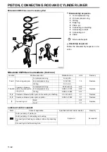


11-76
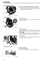
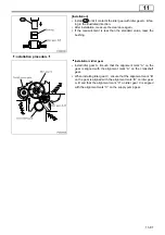
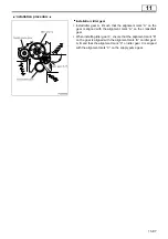
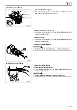
Installation: Air compressor
•
Set the No. 1 cylinder piston at the top dead center of the com-
pression stroke.
•
Align the stamped mark “1” on the air compressor gear with the
projection on the air compressor.
•
While keeping this condition, align the stamped mark “1” with the
scribed line on the rear plate and install the air compressor to
the flywheel housing.
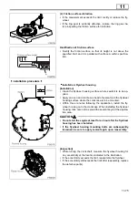
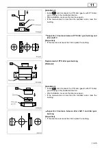
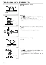
Installation: Rear oil seal
•
Clean the rear oil seal surface where sealant is to be applied.
•
Apply an even and continuous bead of sealant on the rear oil
seal as shown in the illustration.
•
Install the rear oil seal onto the flywheel housing within 3 min-
utes following the application of the sealant. Be careful not to
dislodge the sealant.
CAUTION
• Do not start the engine at least for an hour after the rear oil
seal has been installed.
• If the rear oil seal mounting bolts are subsequently loos-
ened, be sure to apply sealant again upon reassembly.
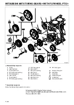
Installation: Ring gear
•
Heat the ring gear evenly with a gas burner or the like until it
reaches approximately 200
°
C.
WARNING
• You may burn yourself if you touch the heated ring gear.
•
Fit the ring gear with the side having non-chamfered portions to-
ward the flywheel.
Installation: Flywheel
CAUTION
• Before installing a bolt, check the number of punch marks
on the bolt head. (Bolts with up to two punch marks can be
reused.)
The number of punch marks indicates the number of times
the bolt has been tightened in the past within the plastic re-
gion. If there are three punch marks (tightened three times
in the past), replace the bolt.
FLYWHEEL
Summary of Contents for 6M70
Page 29: ...M E M O 11 19 11 ...
Page 35: ...M E M O 11 25 11 ...
Page 36: ...11 26 MITSUBISHI 6M70 ROCKER COVER ROCKER AND SHAFT ...
Page 40: ...11 30 MITSUBISHI 6M70 CAMSHAFT AND ROCKER CASE ...
Page 47: ...M E M O 11 37 11 ...
Page 48: ...11 38 MITSUBISHI 6M70 CYLINDER HEAD AND VALVE MECHANISM ...
Page 63: ...M E M O 11 53 11 ...
Page 71: ...M E M O 11 61 11 ...
Page 77: ...M E M O 11 67 11 ...
Page 81: ...M E M O 11 71 11 ...
Page 98: ...11 88 MITSUBISHI 6M70 CRANKSHAFT AND CRANKCASE ...
Page 127: ...M E M O 12 21 12 ...
Page 129: ...M E M O 12 23 12 ...
Page 135: ...M E M O 13 3 13 ...
Page 138: ...13 6 1 1 Mitsubishi 6M70 Supply pump STRUCTURE AND OPERATION ...
Page 150: ...13 18 10 Electronic control unit connection diagram STRUCTURE AND OPERATION ...
Page 151: ...13 13 19 ...
Page 155: ...M E M O 13 23 13 ...
Page 185: ...M E M O 13 53 13 ...
Page 189: ...M E M O 13 57 13 ...
Page 205: ...M E M O 13 73 13 ...
Page 211: ...M E M O 13 79 13 ...
Page 215: ...M E M O 13 83 13 ...
Page 219: ...M E M O 13 87 13 ...
Page 225: ...M E M O 13 93 13 ...
Page 226: ...13 94 INSTALLED LOCATIONS OF PARTS ...
Page 227: ...13 13 95 ...
Page 228: ...13 96 INSTALLED LOCATIONS OF PARTS ...
Page 229: ...13 13 97 ...
Page 230: ...13 98 INSTALLED LOCATIONS OF PARTS ...
Page 231: ...13 13 99 ...
Page 232: ...13 100 MITSUBISHI 6M70 INSTALLED LOCATIONS OF PARTS ...
Page 233: ...13 13 101 ...
Page 234: ...13 102 ELECTRIC CIRCUIT DIAGRAM ...
Page 235: ...13 13 103 ...
Page 236: ...13 104 ELECTRIC CIRCUIT DIAGRAM ...
Page 237: ...13 13 105 ...
Page 238: ...13 106 ELECTRIC CIRCUIT DIAGRAM ...
Page 241: ...14 14 3 1 Mitsubishi 6M70 Cooling System Flow of Coolant STRUCTURE AND OPERATION ...
Page 252: ...14 14 Periphery of Engine DISCONNECTION AND CONNECTION OF HOSES AND PIPES ...
Page 271: ...M E M O 14 33 14 ...
Page 286: ...M E M O 15 13 15 ...
Page 295: ...15 22 7 Installed Locations of Parts TURBOCHARGER CONTROL SYSTEM ...
Page 296: ...15 15 23 ...
Page 297: ...15 24 TURBOCHARGER CONTROL SYSTEM ...
Page 298: ...15 15 25 ...
Page 299: ...15 26 TURBOCHARGER CONTROL SYSTEM ...
Page 300: ...15 15 27 ...
Page 301: ...15 28 TURBOCHARGER CONTROL SYSTEM ...
Page 302: ...M E M O 15 29 15 ...
Page 303: ...15 30 8 Electric Circuit Diagram TURBOCHARGER CONTROL SYSTEM ...
Page 304: ...15 15 31 ...
Page 305: ...15 32 TURBOCHARGER CONTROL SYSTEM ...
Page 306: ...M E M O 15 33 15 ...
Page 330: ...M E M O 15 57 15 ...
Page 340: ...17 6 1 3 Electronic control unit connection diagram STRUCTURE AND OPERATION ...
Page 343: ...M E M O 17 9 17 ...
Page 351: ...M E M O 17 17 17 ...
Page 352: ...17 18 8 Installed Locations of Parts EXHAUST GAS RECIRCULATION SYSTEM ...
Page 353: ...17 17 19 ...
Page 354: ...17 20 EXHAUST GAS RECIRCULATION SYSTEM ...
Page 355: ...17 17 21 ...
Page 356: ...17 22 EXHAUST GAS RECIRCULATION SYSTEM ...
Page 357: ...17 17 23 ...
Page 358: ...17 24 9 Electric Circuit Diagram EXHAUST GAS RECIRCULATION SYSTEM ...
Page 359: ...17 17 25 ...
Page 360: ...17 26 MITSUBISHI 6M70 EGR VALVE EGR MAGNETIC VALVE EGR PIPE AND EGR COOLER ...


