


13
13-89
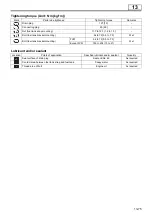
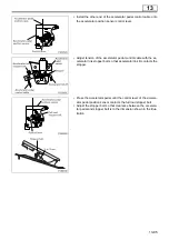
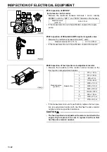
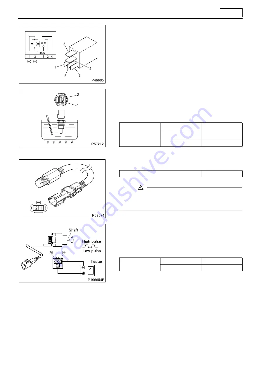
#201 Inspection of relay (normally open 5-pin)
•
Check continuity and operating condition of the relay. Replace
the relay if necessary.
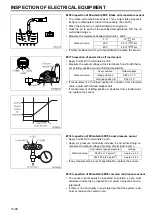
#262 Inspection of
Mitsubishi 6M70
water temperature sensor
•
Place the water temperature sensor in a container filled with en-
gine oil.
•
Heat the oil to each of the specified temperatures. Stir the oil
well while doing so.
•
Measure the resistance between terminals 1 and 2.
•
If either measurement is out of specification, replace the sensor.
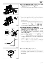
#263 Inspection of
Mitsubishi 6M70
engine speed sensor
•
Measure the resistance between terminals 1 and 2.
•
If the measurement is out of specification, replace the sensor.
CAUTION
• The signal may not output if the sensor tightening torque is
insufficient. Check if the sensor is tightened with the cor-
rect tightening torque. (See Gr11.)
#265 Inspection of vehicle speed sensor
•
With the 24 volts DC applied to terminals 1 and 2, slowly turn the
shaft of the vehicle speed sensor.
•
Measure the maximum voltage (high pulse voltage) and mini-
mum voltage (low pulse voltage) occurring at each specified pair
of terminals.
•
If any measurement is out of specification, replace the sensor.
Standard value
20
°
C
2.45 ± 0.14 k
Ω
80
°
C
0.32 k
Ω
(reference value)
110
°
C
147.1 ± 2
Ω
Standard value (at 25
°
C)
2.2 ± 0.2 k
Ω
Standard value
Low pulse voltage
0.5 V or lower
High pulse voltage
8 ± 1 V
Summary of Contents for 6M70
Page 29: ...M E M O 11 19 11 ...
Page 35: ...M E M O 11 25 11 ...
Page 36: ...11 26 MITSUBISHI 6M70 ROCKER COVER ROCKER AND SHAFT ...
Page 40: ...11 30 MITSUBISHI 6M70 CAMSHAFT AND ROCKER CASE ...
Page 47: ...M E M O 11 37 11 ...
Page 48: ...11 38 MITSUBISHI 6M70 CYLINDER HEAD AND VALVE MECHANISM ...
Page 63: ...M E M O 11 53 11 ...
Page 71: ...M E M O 11 61 11 ...
Page 77: ...M E M O 11 67 11 ...
Page 81: ...M E M O 11 71 11 ...
Page 98: ...11 88 MITSUBISHI 6M70 CRANKSHAFT AND CRANKCASE ...
Page 127: ...M E M O 12 21 12 ...
Page 129: ...M E M O 12 23 12 ...
Page 135: ...M E M O 13 3 13 ...
Page 138: ...13 6 1 1 Mitsubishi 6M70 Supply pump STRUCTURE AND OPERATION ...
Page 150: ...13 18 10 Electronic control unit connection diagram STRUCTURE AND OPERATION ...
Page 151: ...13 13 19 ...
Page 155: ...M E M O 13 23 13 ...
Page 185: ...M E M O 13 53 13 ...
Page 189: ...M E M O 13 57 13 ...
Page 205: ...M E M O 13 73 13 ...
Page 211: ...M E M O 13 79 13 ...
Page 215: ...M E M O 13 83 13 ...
Page 219: ...M E M O 13 87 13 ...
Page 225: ...M E M O 13 93 13 ...
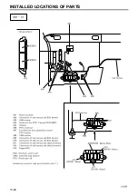
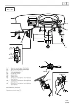
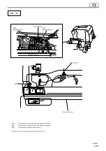
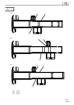
Page 226: ...13 94 INSTALLED LOCATIONS OF PARTS ...
Page 227: ...13 13 95 ...
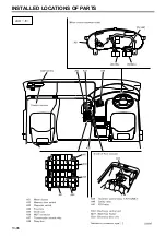
Page 228: ...13 96 INSTALLED LOCATIONS OF PARTS ...
Page 229: ...13 13 97 ...
Page 230: ...13 98 INSTALLED LOCATIONS OF PARTS ...
Page 231: ...13 13 99 ...
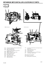
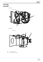
Page 232: ...13 100 MITSUBISHI 6M70 INSTALLED LOCATIONS OF PARTS ...
Page 233: ...13 13 101 ...
Page 234: ...13 102 ELECTRIC CIRCUIT DIAGRAM ...
Page 235: ...13 13 103 ...
Page 236: ...13 104 ELECTRIC CIRCUIT DIAGRAM ...
Page 237: ...13 13 105 ...
Page 238: ...13 106 ELECTRIC CIRCUIT DIAGRAM ...
Page 241: ...14 14 3 1 Mitsubishi 6M70 Cooling System Flow of Coolant STRUCTURE AND OPERATION ...
Page 252: ...14 14 Periphery of Engine DISCONNECTION AND CONNECTION OF HOSES AND PIPES ...
Page 271: ...M E M O 14 33 14 ...
Page 286: ...M E M O 15 13 15 ...
Page 295: ...15 22 7 Installed Locations of Parts TURBOCHARGER CONTROL SYSTEM ...
Page 296: ...15 15 23 ...
Page 297: ...15 24 TURBOCHARGER CONTROL SYSTEM ...
Page 298: ...15 15 25 ...
Page 299: ...15 26 TURBOCHARGER CONTROL SYSTEM ...
Page 300: ...15 15 27 ...
Page 301: ...15 28 TURBOCHARGER CONTROL SYSTEM ...
Page 302: ...M E M O 15 29 15 ...
Page 303: ...15 30 8 Electric Circuit Diagram TURBOCHARGER CONTROL SYSTEM ...
Page 304: ...15 15 31 ...
Page 305: ...15 32 TURBOCHARGER CONTROL SYSTEM ...
Page 306: ...M E M O 15 33 15 ...
Page 330: ...M E M O 15 57 15 ...
Page 340: ...17 6 1 3 Electronic control unit connection diagram STRUCTURE AND OPERATION ...
Page 343: ...M E M O 17 9 17 ...
Page 351: ...M E M O 17 17 17 ...
Page 352: ...17 18 8 Installed Locations of Parts EXHAUST GAS RECIRCULATION SYSTEM ...
Page 353: ...17 17 19 ...
Page 354: ...17 20 EXHAUST GAS RECIRCULATION SYSTEM ...
Page 355: ...17 17 21 ...
Page 356: ...17 22 EXHAUST GAS RECIRCULATION SYSTEM ...
Page 357: ...17 17 23 ...
Page 358: ...17 24 9 Electric Circuit Diagram EXHAUST GAS RECIRCULATION SYSTEM ...
Page 359: ...17 17 25 ...
Page 360: ...17 26 MITSUBISHI 6M70 EGR VALVE EGR MAGNETIC VALVE EGR PIPE AND EGR COOLER ...


