


15
15-35
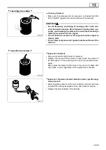
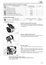
Cleaning procedure
Cleaning: Element
•
Blow a jet of compressed air at a pressure not higher than 685
kPa {7 kgf/cm
2
} against the inside surfaces of the element.
CAUTION
• For the frequency and timing of cleaning, refer to the rele-
vant instruction manual. More frequent cleaning than nec-
essary could damage the element or cause dust and foreign
matter to be sucked into the engine.
• Do not strike the element or hit it against another object to
remove dust.
• Do not blow compressed air against outside surfaces of the
element.
Inspection procedure
Inspection: Element
•
Shine some electric light inside the element.
•
Replace the element if thin spots or broken parts are evident in
the filter paper, or if the packing at the top of the element is dam-
aged.
Also replace the element if the dust on the element is damp with
oily smoke or soot, regardless of the replacement schedule.
Inspection: Operation of dust indicator under specified neg-
ative pressure
•
Apply negative pressure to the dust indicator, and take the read-
ing when the red signal appears in the dust indicator window.
•
Replace the dust indicator if found faulty.
Summary of Contents for 6M70
Page 29: ...M E M O 11 19 11 ...
Page 35: ...M E M O 11 25 11 ...
Page 36: ...11 26 MITSUBISHI 6M70 ROCKER COVER ROCKER AND SHAFT ...
Page 40: ...11 30 MITSUBISHI 6M70 CAMSHAFT AND ROCKER CASE ...
Page 47: ...M E M O 11 37 11 ...
Page 48: ...11 38 MITSUBISHI 6M70 CYLINDER HEAD AND VALVE MECHANISM ...
Page 63: ...M E M O 11 53 11 ...
Page 71: ...M E M O 11 61 11 ...
Page 77: ...M E M O 11 67 11 ...
Page 81: ...M E M O 11 71 11 ...
Page 98: ...11 88 MITSUBISHI 6M70 CRANKSHAFT AND CRANKCASE ...
Page 127: ...M E M O 12 21 12 ...
Page 129: ...M E M O 12 23 12 ...
Page 135: ...M E M O 13 3 13 ...
Page 138: ...13 6 1 1 Mitsubishi 6M70 Supply pump STRUCTURE AND OPERATION ...
Page 150: ...13 18 10 Electronic control unit connection diagram STRUCTURE AND OPERATION ...
Page 151: ...13 13 19 ...
Page 155: ...M E M O 13 23 13 ...
Page 185: ...M E M O 13 53 13 ...
Page 189: ...M E M O 13 57 13 ...
Page 205: ...M E M O 13 73 13 ...
Page 211: ...M E M O 13 79 13 ...
Page 215: ...M E M O 13 83 13 ...
Page 219: ...M E M O 13 87 13 ...
Page 225: ...M E M O 13 93 13 ...
Page 226: ...13 94 INSTALLED LOCATIONS OF PARTS ...
Page 227: ...13 13 95 ...
Page 228: ...13 96 INSTALLED LOCATIONS OF PARTS ...
Page 229: ...13 13 97 ...
Page 230: ...13 98 INSTALLED LOCATIONS OF PARTS ...
Page 231: ...13 13 99 ...
Page 232: ...13 100 MITSUBISHI 6M70 INSTALLED LOCATIONS OF PARTS ...
Page 233: ...13 13 101 ...
Page 234: ...13 102 ELECTRIC CIRCUIT DIAGRAM ...
Page 235: ...13 13 103 ...
Page 236: ...13 104 ELECTRIC CIRCUIT DIAGRAM ...
Page 237: ...13 13 105 ...
Page 238: ...13 106 ELECTRIC CIRCUIT DIAGRAM ...
Page 241: ...14 14 3 1 Mitsubishi 6M70 Cooling System Flow of Coolant STRUCTURE AND OPERATION ...
Page 252: ...14 14 Periphery of Engine DISCONNECTION AND CONNECTION OF HOSES AND PIPES ...
Page 271: ...M E M O 14 33 14 ...
Page 286: ...M E M O 15 13 15 ...
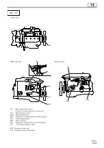
Page 295: ...15 22 7 Installed Locations of Parts TURBOCHARGER CONTROL SYSTEM ...
Page 296: ...15 15 23 ...
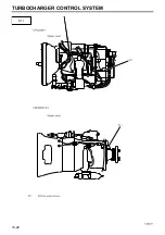
Page 297: ...15 24 TURBOCHARGER CONTROL SYSTEM ...
Page 298: ...15 15 25 ...
Page 299: ...15 26 TURBOCHARGER CONTROL SYSTEM ...
Page 300: ...15 15 27 ...
Page 301: ...15 28 TURBOCHARGER CONTROL SYSTEM ...
Page 302: ...M E M O 15 29 15 ...
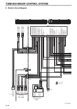
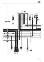
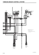
Page 303: ...15 30 8 Electric Circuit Diagram TURBOCHARGER CONTROL SYSTEM ...
Page 304: ...15 15 31 ...
Page 305: ...15 32 TURBOCHARGER CONTROL SYSTEM ...
Page 306: ...M E M O 15 33 15 ...
Page 330: ...M E M O 15 57 15 ...
Page 340: ...17 6 1 3 Electronic control unit connection diagram STRUCTURE AND OPERATION ...
Page 343: ...M E M O 17 9 17 ...
Page 351: ...M E M O 17 17 17 ...
Page 352: ...17 18 8 Installed Locations of Parts EXHAUST GAS RECIRCULATION SYSTEM ...
Page 353: ...17 17 19 ...
Page 354: ...17 20 EXHAUST GAS RECIRCULATION SYSTEM ...
Page 355: ...17 17 21 ...
Page 356: ...17 22 EXHAUST GAS RECIRCULATION SYSTEM ...
Page 357: ...17 17 23 ...
Page 358: ...17 24 9 Electric Circuit Diagram EXHAUST GAS RECIRCULATION SYSTEM ...
Page 359: ...17 17 25 ...
Page 360: ...17 26 MITSUBISHI 6M70 EGR VALVE EGR MAGNETIC VALVE EGR PIPE AND EGR COOLER ...


