


3. SIGNALS AND WIRING
3 - 21
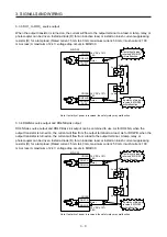
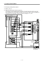
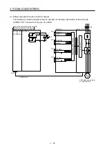
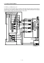
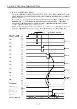
3.8.3 MR-J4-_A_-RJ/MR-J4-DU_A_-RJ
The following connection diagram shows an operation of the safety observation function using input devices
assigned to pins of the CN10A and CN10B connectors with a safety controller. By diagnosis of input signals,
the servo amplifier complies with safety level Category 4, PL e, SIL 3.
A1
(24V)
A2
(0V)
24 V
0 V
FLEXB
US+
FLEXB
US+
24 V
0 V
X1
X2
A1
(24V)
Q1
Q2
Q3
A2
(0V)
WS0-CPU0
WS0-XTIO
CN10A
CN10B
S1
CN10A
CN10B
DO24VA
DO24VB
DO_A
DO_B
DICOMA
DI_A
DICOMB
DI_B
CN1A
CN1/2
MR-D30
MR-J4-_A_-RJ/
MR-J4-DU_A_-RJ
KM1
QX_
COM
I1
I2
I3
I4
Application
Application
Safety controller MELSEC-WS series
CPU module WSO-CPU0
Safety I/O combined module WS0-XTIO
Control circuit
Safety observation function
General-purpose
interface
Deceleration
command
Servo
motor
DIO control
KM1: Magnetic contactor
S1: Safety switch
Summary of Contents for MR-D30
Page 13: ...4 MEMO ...
Page 41: ...1 FUNCTIONS AND CONFIGURATION 1 28 MEMO ...
Page 141: ...6 DISPLAY 6 2 MEMO ...
Page 153: ...MEMO ...