


3. SIGNALS AND WIRING
3 - 5
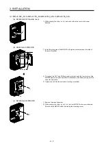
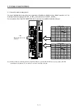
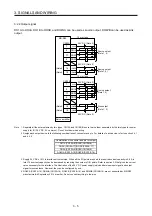
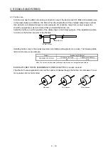
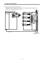
3.2.2 Output signal
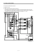
DO1A to DO3A, DO1B to DO3B, and DO4NA can be used as source output. DO4PB can be used as sink
output.
Servo amplifier
8
DO1A
17
DO2A
9
DO3A
CN10A
MR-D30
7
DO24VA
24 V DC (Note 3)
10 m or less
10 m or less
8
DO1B
17
DO2B
9
DO3B
CN10B
7
DO24VB
24 V DC (Note 3)
RA5
RA6
RA7
RA1
RA2
RA3
Source output
(Note 1, 2)
Source output
(Note 1, 2)
16
(Note 4)
(Note 4)
(Note 4)
(Note 4)
DO4PA
18
DO4NA
16
DO4PB
18
DO4NB
RA4
24 V DC (Note 3)
Source output
(Note 1, 2)
24 V DC (Note 3)
RA8
Sink output
(Note 1, 2)
Note 1. Separate all the external wires by two types, CN10A and CN10B. Be sure to wire them separately by the two types for power
supply for IO (24 V DC, 0 V common). Do not mix them when wiring.
2.
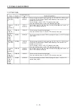
Assign each output device to the following combinations of connector and pin. For details of each device, refer to section 4.4.1
and 4.4.2.
Combination of connector and pin for output
DO1A (CN10A-8)/DO1B (CN10B-8)
DO2A (CN10A-17)/DO2B (CN10B-17)
DO3A (CN10A-9)/DO3B (CN10B-9)
DO4NA (CN10A-18)/DO4PB (CN10B-16)
3. Supply 24 V DC ± 10% to interfaces from outside. When all the I/O points are used, the required current capacity is 0.8 A in
total. The current capacity can be decreased by reducing the number of I/O points. Refer to section 3.3 that gives the current
value necessary for the interface. The illustration of the 24 V DC power supply is divided between input signal and output
signal for convenience. However, they can be configured by one.
4. DO4PA (CN10A-16), DO4NA (CN10A-18), DO4PB (CN10B-16), and DO4NB (CN10B-18) are not supported by MR-D30
manufactured in September, 2014 or earlier. Do not connect anything to the pins.
Summary of Contents for MR-D30
Page 13: ...4 MEMO ...
Page 41: ...1 FUNCTIONS AND CONFIGURATION 1 28 MEMO ...
Page 141: ...6 DISPLAY 6 2 MEMO ...
Page 153: ...MEMO ...