


2. INSTALLATION
2 - 2
2.1 Installation direction and clearances
CAUTION
The equipment must be installed in the specified direction. Otherwise, it may
cause a malfunction.
Leave specified clearances between the servo amplifier/MR-D30 and the cabinet
walls or other equipment. Otherwise, it may cause a malfunction.
POINT
For the installation direction and clearances of the MR-J4-DU_-RJ, refer to "MR-
CV_/MR-CR55K_/MR-J4DU_(-RJ) Instruction Manual".
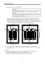
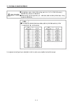
(1) Installation clearances of the servo amplifier
(a) Installation of one servo amplifier
40 mm or more
10 mm
or more
10 mm
or more
(Note 2)
40 mm
or more
(Note 1)
Servo amplifier
Cabinet
Cabinet
80 mm
or more
Wiring allowance
Top
Bottom
Note 1. For the 11 kW to 22 kW servo amplifiers, the clearance between the bottom and the ground will be 120 mm or more.
2. When mounting MR-J4-500_-RJ, maintain a minimum clearance of 25 mm on the left side.
Summary of Contents for MR-D30
Page 13: ...4 MEMO ...
Page 41: ...1 FUNCTIONS AND CONFIGURATION 1 28 MEMO ...
Page 141: ...6 DISPLAY 6 2 MEMO ...
Page 153: ...MEMO ...