


3. SIGNALS AND WIRING
3 - 7
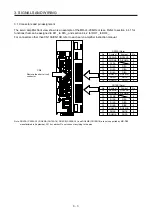
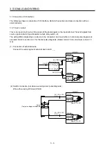
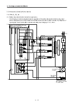
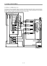
(3) Switch connection (when executing a test pulse diagnosis)
The pulses for diagnosis will be outputted from PLSA and PLSB. Wire so that the pulse signals
outputted from PLSA and PLSB pass through the switch.
Approx. 5.6 k
Ω
MR-D30
Approx. 5.6 k
Ω
DC24VA
PLSA
DICOMA
DI1A, etc.
CN10A
DC24VB
PLSB
DICOMB
DI1B, etc.
CN10B
24 V DC ± 10%
0.8 A
24 V DC ± 10%
0.8 A
Switch
(Test pulse diagnosis enabled)
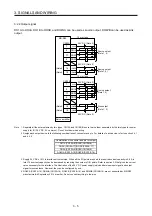
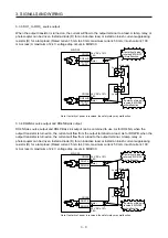
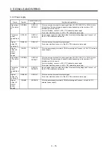
3.3.2 Sink input
This is an input circuit whose photocoupler cathode side is input terminal. Transmit signals from sink (open
collector) type transistor output, relay switch, etc.
The wiring differs depending on a device to be connected, and on whether or not a test pulse diagnosis is
executed. Refer to section 4.4.1 for the test pulse diagnosis. (Rated current: 5 mA, maximum current: 10
mA)
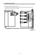
(1) Connection of external device
Connect the output signal of external device to DI _ _.
Approx. 5.6 k
Ω
MR-D30
Approx. 5.6 k
Ω
DICOMA
DI1A, etc.
CN10A
CN210B
DICOMB
DI1B, etc.
24V IN
0V IN
Control
output 1
Control
output 2
External device
24 V DC 5 mA
24 V DC 5 mA
24 V DC
Summary of Contents for MR-D30
Page 13: ...4 MEMO ...
Page 41: ...1 FUNCTIONS AND CONFIGURATION 1 28 MEMO ...
Page 141: ...6 DISPLAY 6 2 MEMO ...
Page 153: ...MEMO ...