


5. PARAMETERS
5 - 15
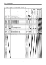
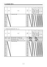
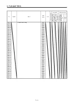
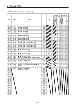
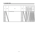
No.
Symbol
Name and function
Initial
value
[unit]
Setting
range
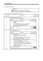
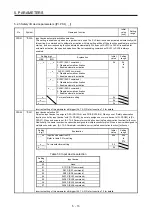
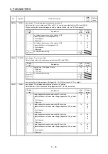
PSD07
**SDI6
Input device selection DI6
Select an input device to assign to DI6A (CN10A-15) and DI6B (CN10B-15). Setting method is the same as [Pr.
PSD02].
Setting
digit
Explanation
Initial
value
Setting
range
_ _ x x Input device selection DI6
Refer to table 5.3 for setting.
00h 00h
to
07h
_ x _ _ For manufacturer setting
0h
x _ _ _
0h
Incorrect setting of this parameter will trigger [AL. 7A.3]. Refer to section 7.2 for details.
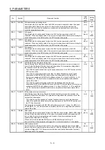
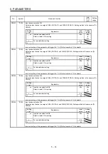
PSD08
**SDO1
Output device selection DO1
Select an input device to assign to DO1A (CN10A-8) and DO1B (CN10B-8).
Setting
digit
Explanation
Initial
value
Setting
range
_ _ x x Output device selection DO1
Refer to table 5.4 for setting.
00h 00h
to
0Ah
_ x _ _ For manufacturer setting
0h
x _ _ _
0h
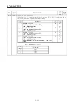
Table 5.4 Output device selection
Setting
value
Output device
_ _ 0 0
None
_ _ 0 1
STOS (STO output)
_ _ 0 2
SS1S (SS1 output)
_ _ 0 3
SS2S (SS2 output)
_ _ 0 4
SLS1S (SLS1 output)
_ _ 0 5
SLS2S (SLS2 output)
_ _ 0 6
SLS3S (SLS3 output)
_ _ 0 7
SLS4S (SLS4 output)
_ _ 0 8
SSMS (SSM output)
_ _ 0 9
SOSS (SOS output)
_ _ 0 A
SBCS (SBC output)
Incorrect setting of this parameter will trigger [AL. 7A.3]. Refer to section 7.2 for details.
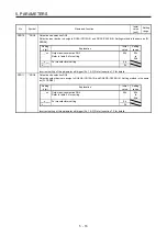
PSD09
**SDO2
Output device selection DO2
Select an input device to assign to DO2A (CN10A-17) and DO2B (CN10B-17). Setting method is the same as
[Pr. PSD08].
Setting
digit
Explanation
Initial
value
Setting
range
_ _ x x Output device selection DO2
Refer to table 5.4 for setting.
00h 00h
to
0Ah
_ x _ _ For manufacturer setting
0h
x _ _ _
0h
Incorrect setting of this parameter will trigger [AL. 7A.3]. Refer to section 7.2 for details.
Summary of Contents for MR-D30
Page 13: ...4 MEMO ...
Page 41: ...1 FUNCTIONS AND CONFIGURATION 1 28 MEMO ...
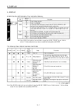
Page 141: ...6 DISPLAY 6 2 MEMO ...
Page 153: ...MEMO ...