

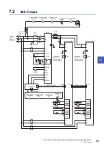


8 CONVERTER UNIT TROUBLESHOOTING
8.3 Handling methods for alarms/warnings
81
8
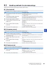
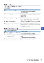
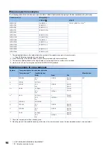
[75_Overvoltage]
• The value of the bus voltage exceeded the specified value.
200 V class: 420 V DC
400 V class: 840 V DC
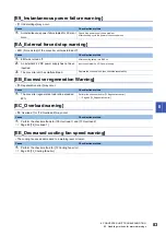
[76_Switch setting error]
• The setting of the rotary switch is incorrect.
Cause
Check/action method
1.
The regeneration capacity is insufficient.
Set a longer deceleration time constant, then check the repeatability.
If the error does not repeat, take corrective actions as follows:
• Check the operation pattern.
• Use a converter unit with a larger capacity.
2.
The power supply voltage is too high.
Check if the voltage of the input power supply exceeds the upper limit of the
permissible voltage. If the power supply voltage exceeds the upper limit, reduce the
power supply voltage.
200 V class: 297 V AC
400 V class: 594 V AC
3.
The servo motor power cable has a ground fault
or has shorted.
Check if the servo motor power cable has a ground fault. If the servo motor power
cable has a ground fault, correct the wiring.
Check if the servo motor power cable has shorted. If the servo motor power cable
has shorted, replace the servo motor power cable.
4.
The servo motor has a ground fault.
After disconnecting the servo motor power cables on the servo motor side, check the
insulation between phases (U/V/W/E). If the servo motor has a ground fault or has
shorted, replace the servo motor.
5.
There is a problem with the surrounding
environment.
Check the noise, ambient temperature, and other conditions, and implement
appropriate countermeasures for the cause. If there is noise, take countermeasures
to reduce the noise.
For noise reduction techniques, refer to the following.
Page 96 Noise reduction techniques
Cause
Check/action method
1.
The value set with the rotary switch (SW1) is set
out of the settable range.
Check the settings of the rotary switches.
For details on the rotary switch settings, refer to the following.
Page 28 Converter unit switch settings and operation panel
2.
Forced stop has been input when the rotary switch
is set to disable forced stop.
Check the forced stop wiring and rotary switch setting.
For details on the forced stop wiring and the rotary switch settings, refer to the
following.
Page 28 Converter unit switch settings and operation panel
Page 32 Example power circuit connections
3.
The converter unit has malfunctioned.
Replace the converter unit, then check the repeatability.


