


64
6 CHARACTERISTICS
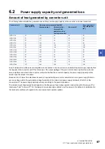
6.1 Overload protection characteristics
6
CHARACTERISTICS
6.1
Overload protection characteristics
An electronic thermal is built into the converter unit to protect the converter unit from overloads.
[7E Overload 1] occurs when overload operation exceeds the electronic thermal protection curve shown in this section. [7F
Overload 2] occurs when operation continues above the rated speed and rated torque. Use the equipment within the area on
the left side of the graph.
Graph of overload protection characteristics
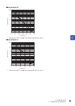
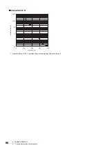
The table lists the converter units and corresponding graphs of overload protection characteristics.
■
Characteristic A
*1 A resistive force of 100 % indicates the continuous rating of the converter unit.
Converter unit
Graph of overload protection characteristics
MR-CV11K
MR-CV30K
MR-CV37K
MR-CV45K
MR-CV11K4
MR-CV30K4
MR-CV37K4
MR-CV45K4
Characteristic A
MR-CV18K
MR-CV18K4
Characteristic B
MR-CV55K
Characteristic C
MR-CV55K4
MR-CV75K4
Characteristic D
0.1
1
0
100
200
300
400
500
600
10000
1000
100
10
Load ratio [%]
*1
Operation time [s]


