


5 SIGNALS AND WIRING
5.2 Explanation of power supply system
39
5
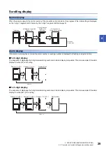
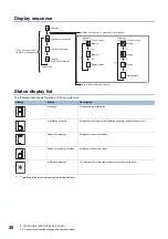
Power-on sequence
Power-on procedure
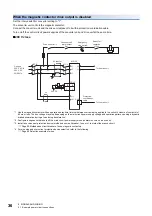
1.
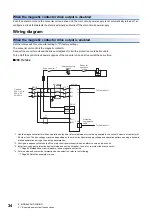
Wire the power supply using a magnetic contactor between the power supply and the main circuit power supply (L1/L2/
L3) of a servo amplifier by referring to the following section. Configure the circuit to switch off the magnetic contactor as
soon as an alarm occurs using an external sequence.
Page 32 Example power circuit connections
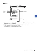
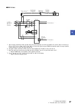
2.
Switch on the control circuit power supply (L11 and L21) of the converter unit and drive unit simultaneously with or before
switching on the main circuit power supply. If the main circuit power supply is not on, the drive unit display shows the
corresponding warning. However, the warning will disappear and the equipment will operate properly if the main circuit is
powered on.
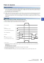
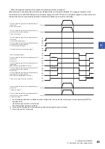
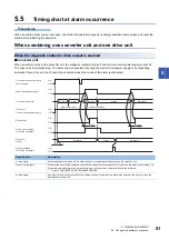
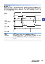
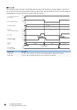
Timing chart
■
When combining one converter unit and one drive unit
• When the magnetic contactor drive output is enabled and remains ready-on
The main circuit power supply is not shut off even in the servo-off status.
*1 If an electromagnetic brake is installed externally, configure the circuit so that the electromagnetic brake operates with MBR as
described below.
ON: Electromagnetic brake is not activated
OFF: Electromagnetic brake is activated
*2 Give a position command after the externally-installed electromagnetic brake is released.
*3 When in the position control mode.
*4 In the drive unit parameters, set the delay time (Tb) from when the MBR shuts off at servo-off until base circuit shut-off.
OFF
ON
OFF
(95 ms)
ON
OFF
(3 s)
Tb
*4
ON
OFF
ON
ON
OFF
ON
OFF
0 r/min
0 r/min
*2
Main circuit power supply
Base circuit
Drive unit
control circuit power supply
MBR
(Electromagnetic brake interlock)
*1
Position command
*3
Servo motor speed
Servo-on command (From the controller)
Converter unit control circuit power supply


