


50
5 SIGNALS AND WIRING
5.4 Signal (device) explanation
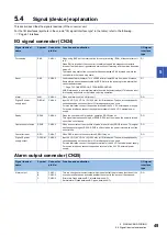
Magnetic contactor control connector (CN23)
Signal (device)
name
Symbol
Connector
pin No.
Function and application
I/O signal
interface
type
Magnetic contactor
drive output
MC1
CN23-1
Connect to the coil of the magnetic contactor and the power supply for magnetic
contactor control.
When the converter unit receives a start command from the drive unit, a short circuit
occurs between MC1 (CN23-1 pin) and MC2 (CN23-3 pin).
If the magnetic contactor control connector (CN23) is not used for control, set the rotary
switch for converter setting (SW1) of the converter unit to "1". (
unit switch settings and operation panel)
MC2
CN23-3


