


38
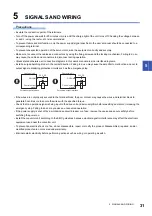
5 SIGNALS AND WIRING
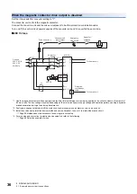
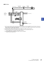
5.2 Explanation of power supply system
5.2
Explanation of power supply system
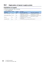
Explanation of signals
For the layout of terminal blocks, refer to the following.
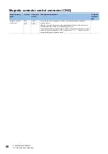
Connection destination
(application)
Symbol
Terminal
block
Description
MR-CV11K to MR-CV55K
MR-CV11K4 to MR-CV75K4
Main circuit power supply
L1/L2/L3
TE1
Supply 3-phase 200 V AC to 240 V AC, 50
Hz/60 Hz power to L1, L2, and L3.
Supply 3-phase 380 V AC to 480 V AC, 50
Hz/60 Hz power to L1, L2, and L3.
Control circuit power supply
L11/L21
TE3
Supply 1-phase 200 V AC to 240 V AC, 50
Hz/60 Hz power to L11 and L21.
Supply 1-phase 380 V AC to 480 V AC, 50
Hz/60 Hz power to L11 and L21.
Drive unit
L+/L-
TE2
Connect them with L+ and L- of the drive unit.
Use the bus bar.
Protective earth (PE)
PE
Connect this terminal to the protective earth (PE) of the cabinet.


