


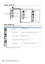


36
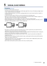
5 SIGNALS AND WIRING
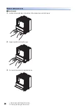
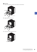
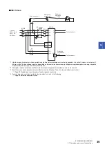
5.1 Example power circuit connections
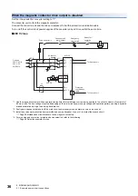
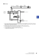
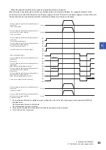
When the magnetic contactor drive output is disabled
Set the rotary switch for converter setting to "1".
The converter unit controls the magnetic contactor.
Connect the converter unit and the drive unit adjacent to it with a protection coordination cable.
Turn on/off the control circuit power supplies of the converter unit and drive unit at the same time.
■
200 V class
*1 Use the magnetic contactor with an operation delay time (interval between current being applied to the coil until closure of contacts) of
80 ms or less. The bus voltage may drop depending on the main circuit power supply voltage and operation pattern, causing a dynamic
brake deceleration during a forced stop deceleration.
*2 Configure a sequence that shuts off the main circuit power supply when an alarm occurs on a drive unit.
*3 Install an overcurrent protection device (molded-case circuit breaker, fuse, etc.) to protect the branch circuit.
Page 93 Molded-case circuit breakers, fuses, magnetic contactors
*4 For wire size and overcurrent protection device selection, refer to the following.
Page 89 Selection example of wires
L1
L2
L3
B
C
B
C
L11
L21
L+
L-
SK
MCCB
RA1
MC
*1
CN25
CN4
*3*4
MR-CV_
RA1
MC
Ready for
operation
off/on
Emergency
stop switch
AC reactor
Protection
coordination
cable
To the drive unit
To the drive unit
3-phase
200 V AC to
240 V AC
50/60 Hz
Converter unit
alarm output
Drive unit error
*2
24 V DC


