3. INSTALLATION
3.3 Installation
I
-7
3.3 Installation
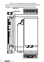
Each unit is installed in the sealed structure cabinet as a principle. When installing into the cabinet, refer
to the following drawings to consider the unit's heat dissipation and wiring, and secure enough space for
ventilation.
(1) Install the unit vertically so that the front is visible.
(2) Refer to the following drawings to consider the unit's heat dissipation and wiring, and secure enough
space for ventilation.
(Top)
Control
unit
Servo drive unit Spindle drive unit
30mm
or more
0
OPEN
CBUS 2
CBUS 1
M I T S U B I S H I
M D S - B - S V J 2
M I T S U B I S H I
M D S - B - S V J 2
4
ST No.
POWER
RUN
CPU-E
S T O P
R U N
RIO
ER R 1
ER R 2
Remote I/O unit
(FCU6-DX561)
Remote I/O unit
(FCUA-DX1
)
100mm or more
(heat dissipation
allowance)
50mm or more
(heat dissipation
allowance)
50mm
or more
10mm or more
10mm or more 10mm
or more
15mm or more
(wiring allowance)
15mm or more
(wiring allowance)
150mm or more
(heat dissipation,
wiringallowance)
100mm or more
(heat dissipation,
wiring allowance)
(Bottom)
Install the unit on noncombustible material.
Installation directly on or near combustible material may lead to fires.
Always observe the installation direction.
Do not install or operate a unit that is damaged or that has missing parts.
The unit is a precision device so do not drop or apply strong impacts on it.
CAUTION
Downloaded from


