5. CONNECTION OF UNIT
5.6 Connection of Encoder Speed Signal
I
-15
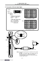
5.6 Connection of Encoder Speed Signal
Encoder
ENC1/2
(Note)
Refer to
following
drawing.
4
STOP
RUN
PC1
PC1
∗
PC3
PC3
∗
PC4
PC4
∗
PC2
PC2
∗
ENC1ENC2
Encoder
OSE1024-3-15-68
1
10
11
20
ENC1/2
DI-L
DO-L
DCIN
CN8
CN6
R000 cable
F040
/
F041 cable
Station No.
setting
Channel 1
Connector
ENC pin No.
Spindle amplifier
Channel 3
Channel 4
Channel 2
DI-R
1
10
11
20
GND
PC1
GND
PC3
1
2
3
4
5
6
7
8
9
10
11
12
13
14
15
16
17
18
19
20
I
I
I
I
GND
PC1*
GND
PC3*
GND
PC2
GND
PC4
1
2
3
4
5
6
7
8
9
10
11
12
13
14
15
16
17
18
19
20
I
I
I
I
GND
PC2*
GND
PC4*
ENC1
ENC2
Connect the connector shell (frame) to
the FG via the pattern on the PCB.
Connect the connector shell (frame) to
the FG via the pattern on the PCB.
<PCB side connector type>
Receptacle : 52822-4011
Maker :
Molex
<Cable side connector type>
Plug :
10120-3000VE
Shell : 10320-52F0-008
Recommended maker:
Sumitomo
3M
(Note)
The encoder speed signal is connected via the spindle
amplifier.
As there is no power supply, the encoder cannot be
directly connected to the connectors ENC1/ENC2.
A dedicated cable is required to use channels 3/4 of the
connectors ENC1/ENC2.
Downloaded from


