2. FAULT DIAGNOSIS
2.2 Troubleshooting
II
-9
2.2.3
Behavior of independent faults
The EN954-1 Category 3 machine system must be designed so that the safety functions are not
disabled when one of the safety-related parts fails independently. Precautions for the designs and
examples of the behavior when an independent fault occurs are listed below.
<Precautions for design>
Set a safety circuit outside the FCU6-DX561 so that the entire system works safely even if an
external power supply error or FCU6-DX561 fault, etc., occurs.
Detect a mismatch between PLCs or stop the machine system according to the behavior.
(1) Always configure circuits outside of the FCU6-DX561, such as an emergency stop circuit,
protection circuit, interlock circuit for reciprocating operations such as forward/reverse run, and
machine damage preventing interlock circuits such as positioning upper/lower limits.
(2) If the FCU6-DX561 CPU detects and error with a self-diagnosis function, such as a watch dog
timer error, all DO outputs will turn OFF. Output control may be disabled when errors occur at
sections, such as the input/output control section, which cannot be detected by the
FCU6-DX561 CPU.
Design an external circuit or mechanism so that the machine will operate safely in this case.
(3) The output may stay ON or may stay OFF depending on faults that occur in the output circuit's
photo coupler or transistor.
Design an external circuit or mechanism for the output signals that could lead to accidents so
that the machine will operate safely.
Example of behavior during independent fault occurrence
Cause of fault
Behavior
The 24VDC power for control turned OFF (failed).
The power cable was disconnected (broken).
The PLC will stop.
The DO output will turn OFF.
The 24VDC power for DO turned OFF (failed)
The DO output will turn OFF.
The remote I/O cable was disconnected (broken).
The remote I/O cable is affected by noise.
The RIO communication will stop.
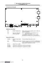
(The communication alarm display "RIOERR1" or
"RIOERR2" LED will turn ON.)
The contact of the relay connected to DI fused, or
a contact fault has occurred due to a rough
contact surface.
Regardless of the machine signal's ON or OFF
state, the DI input will turn OFF or ON.
The DI cable was disconnected (broken).
The DI input will turn OFF.
The contact of the relay connected to DI fused, or
a contact fault has occurred due to a rough
contact surface.
Regardless of the DO output's ON or OFF state,
the relay will turn OFF or ON.
The DO cable was disconnected (broken).
The DO output will turn OFF.
The encoder failed.
The spindle amplifier's encoder I/F circuit failed.
The encoder input data will become an abnormal
value or will not be input.
The encoder cable between the encoder and
spindle amplifier was disconnected (broken).
The encoder input data will not be input.
(The encoder detection speed will become 0.)
The encoder cable between the spindle amplifier
and FCU6-DX561 was disconnected (broken).
The encoder input data will not be input.
(The encoder detection speed will become 0.)
A watch dog timer error occurred in the
FCU6-DX561.
The PLC will stop, and the RIO communication will
stop.
The DO output will turn OFF.
(The CPU error display "CPU-E" will turn ON.)
A fault occurred in the internal 5V output
generation circuit.
The PLC will stop, and the RIO communication will
stop.
The DO output will turn OFF.
(The 5VDC output display "POWER" will turn
OFF.)
Downloaded from

